CTI 2572-B / 2500C-2572-B Installation and Operation Manual 7
The function of the switches is described below.
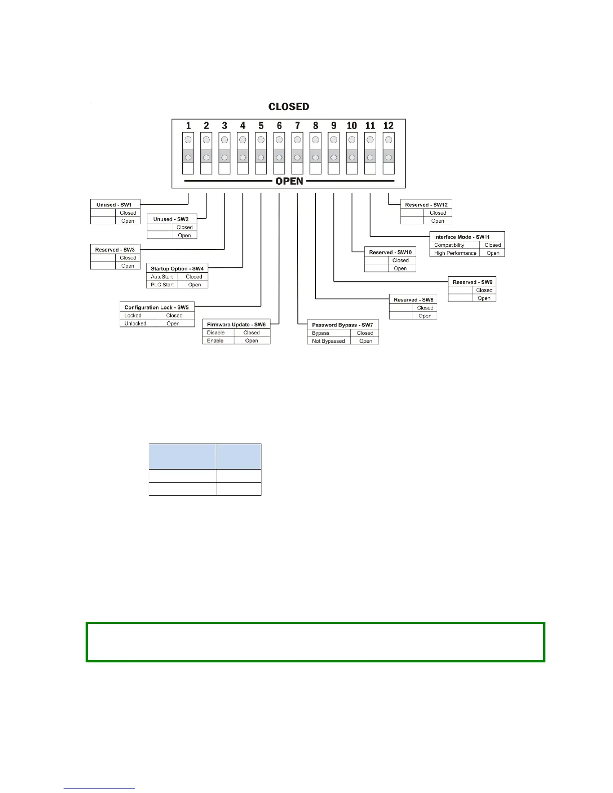
Figure 2. Option Switches
SW1, SW2: These switches are unused and may be set to any position with no effect.
SW3: This switch position is reserved for future use. It should be set to the open position to prevent a future
use from unintentionally affecting the module operation.
SW4: Startup Option: This switch selects how the 2572-B module will start network services.
In the AUTOSTART position, the module will automatically start up using parameters stored in non-volatile
(flash) memory.
In the PLC START position, the module will start up in a limited function mode, using the parameters stored in
flash. It will then wait for PLC logic to trigger the START NETWORK SERVICES command before starting the network
services that allow access to the PLC. CHAPTER 4. describes the PLC logic required. When the command is
successfully completed, the IP parameters obtained from the PLC will be written to non-volatile (flash)
memory.
NOTE:
When using the PLC Start Option, the PLC must be in run mode before the module will start up in
full function mode.
 Loading...