CTI 2572-B / 2500C-2572-B Installation and Operation Manual 28
• WY5-WY8 contain the starting V Memory addresses of up to four Command Blocks, described in the
following section.
7.2. Command Blocks
Command Blocks specify the command to be executed along with parameters defining the execution. A
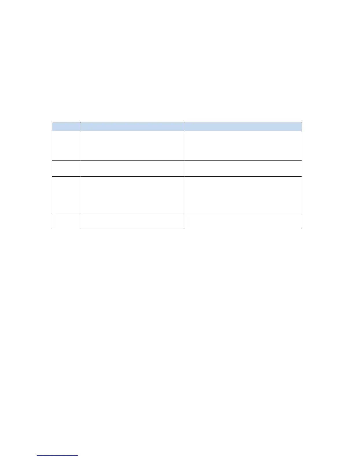
command block consists of up to 15 contiguous words of V memory, as illustrated below. The first three
words are common to all command blocks. The remaining words contain command parameters, which vary
with each command. See the Illustration below.
0 Command Error Word When an error occurs, the module will
write an error code to this offset. User
logic should clear this error code (set it to
0) after a successful attempt.
1 Command The command code specifies the function
2 Connection Number (19291 -
19299)
The connection number is used by the
2572-B module to identify a command
instance. Connection numbers must be
unique and be within the range allowed by
3 -15 Command Parameters Values that specify how the command will
In this manual, when command blocks are specified, a bold entry indicates a required value. An entry that is
not bold represents a recommended value that you should use unless you have reason to do otherwise.
Values for the command block entries are shown in both hexadecimal and decimal (integer) format. Using
your PLC programming software, you can configure a chart to display the values either way.