CTI 2572-B / 2500C-2572-B Installation and Operation Manual 13
CHAPTER 3. MODULE OPERATION
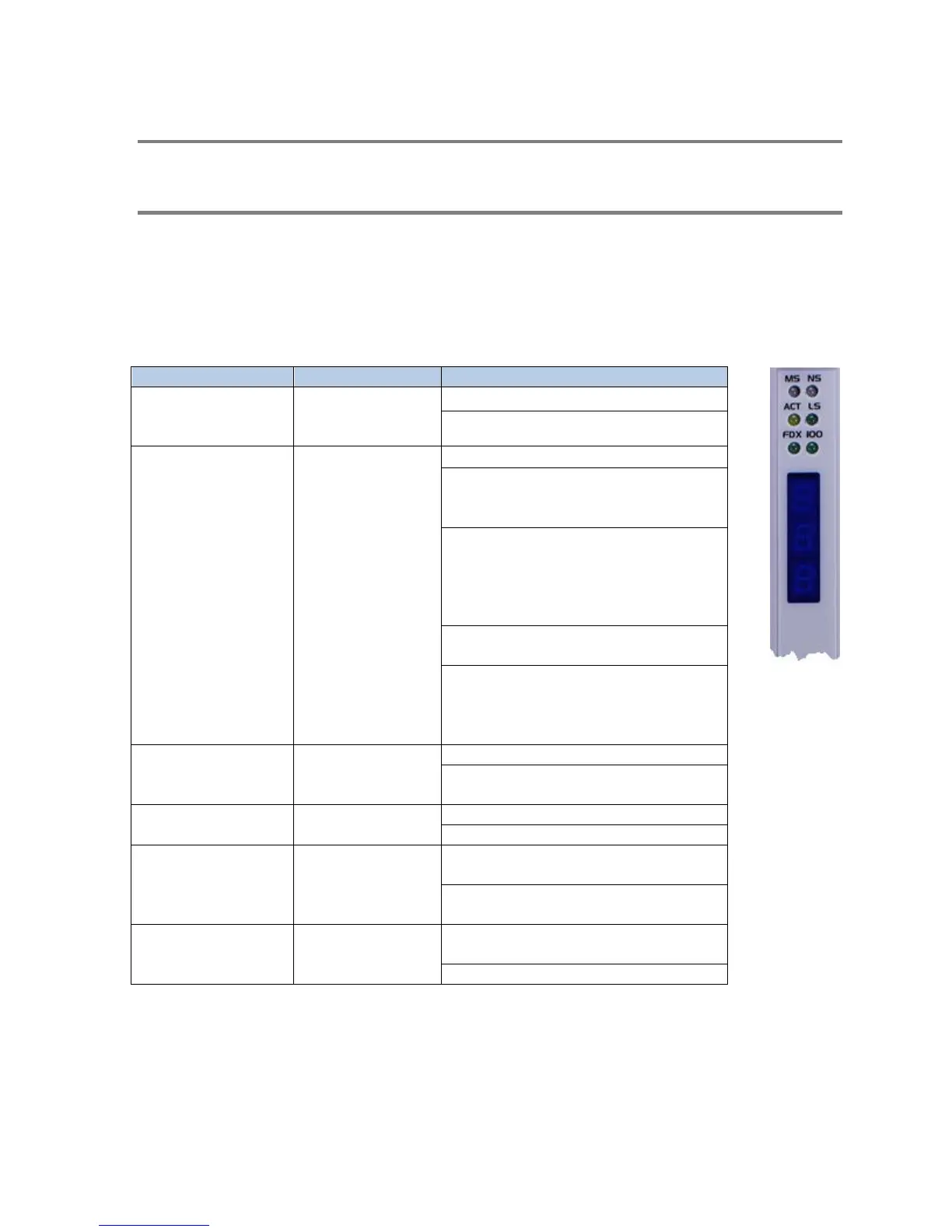
3.1. Front Panel Features
Status LED Indicators
The following table describes the module LED indicators.
operational state of
Off: Application Firmware not started
Steady Green: Module Operational
of the network
interface.
Off: Network Interface not started
Flashing Green: The module is waiting on
PLC logic to start network services (PLC
Flashing Red: The module is waiting on
the PLC logic to start network services.
The IP address initially read from flash is a
duplicate of another IP host on the
Steady Green: The network interface is
operational.
Steady Red: The network interface is
operational. The module IP address is a
duplicate of another IP host with the same
IP address is on the network.
the Ethernet Link.
Off: No Ethernet activity detected.
Flashing: Ethernet frames are being
received and/or transmitted.
Indicates status of
Physical Link.
Off: Ethernet link not operational.
On: Ethernet Link is operational.
link duplex mode.
Off: Operating in half duplex mode or not
connected to network.
Steady Green: Operating in full duplex
mode.
Ethernet baud rate.
Off: Operating at 10Mb or not connected
to a network.
 Loading...