CTI 2572-B / 2500C-2572-B Installation and Operation Manual 22
6.2. Tag Types Supported
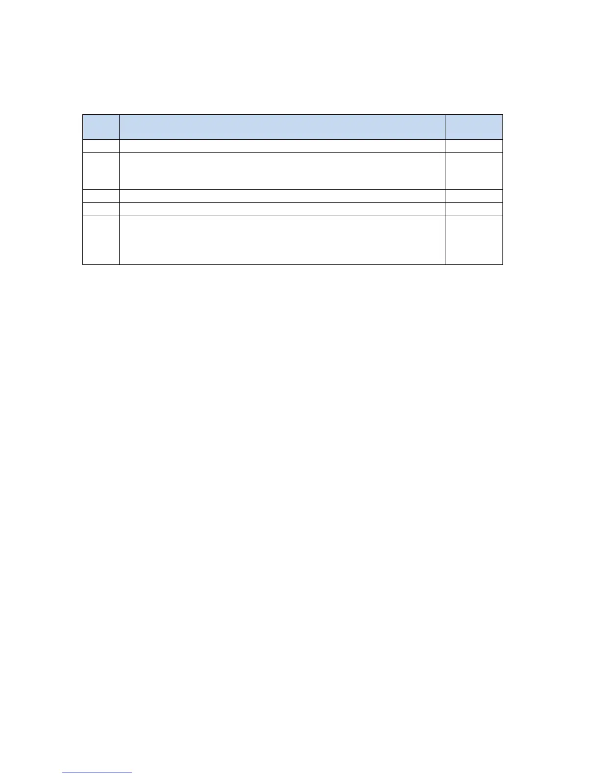
The following table lists the Tag Types supported by the 2572-B EIP server.
V Signed: Accesses a V memory register as a 16 bit signed integer
V Unsigned: Accesses a V memory register as a 16 bit unsigned integer. NOTE:
The Control Logix processor does not support 16 bit unsigned integer as a data
type. (See VE Tag Type below)
V Float: Accesses a pair of V memory registers as a 32 bit floating point number
V Long: Accesses a pair of V memory registers as a 32 bit signed integer
V Extended: Converts between a V memory 16 bit unsigned integer and a 32
bit signed integer CIP data element. NOTE: This Tag Type is specifically for
controllers that do not support 16 bit unsigned integers See the following
section for more information.
Figure 5. V memory Tag Types
V Extended (VE)
VE is a special Tag Type created for controllers that do not support the 16 bit unsigned integer data type. For
Data Table Read operations, it converts unsigned integers stored in a V memory register to a 32 bit signed
integers that can be read by the client controller. For Data Table Write operations, it converts one or more 32
bit signed integers sent by the client to a 16 bit unsigned integers, each stored in a single V memory location.
The following restrictions are placed on data written to V memory using this Tag Type:
1. The value must be a positive number or 0.
2. The maximum value is 65,535 (0xFFFF).
Values that do not meet these requirements will be rejected by the 2572-B EIP server.
6.3. 2572-B Configuration
The EIP Server starts automatically when the module is started up. No additional configuration is required.
6.4. Application Example
The following example illustrate how to configure a Control Logix system to communicate with the 2572-B.
The example reads unsigned integers stored in V memory and writes a block of signed integers to V memory.
The following steps are required to configure the Control Logix system:
1. Define Control Logix tag names that you want to use to hold the data you will read from the 505 PLC and
data you will write to the 505 PLC. For accessing multiple V memory locations, you will need to dimension
the tag as an array.
2. Create Message Blocks in your Control Logix program.
3. Configure each Message Block by selecting the following:
• Message Type: CIP Data Table Read or CIP Data Table Write
• Source Element: For a read operation, this is the 505 Tag Name. For a Write operation this is the Control
Logix Tag Name.