• If the rotation stops, adjust the ferrule up or down
the control rod as necessary to align with the hole
in the transmission control arm, Re-insert the
ferrule into the hole in the control arm and secure
with the internal cotter pin.
• If necessary, repeat the previous two steps to
adjust the other transmission control rod.
• Lower the tractor and remove the jack.
TRACTOR HIGH SPEED TRACKING
If the tractortracks to one side withboth drive control
levers fully forward, adjust the control levers as
follows:
• Check for proper and balanced air pressure in
both front and rear tires. Refilltiresif necessary.
• Perform the first three steps in the previous sub-
section,Tractor Creeping, to verifythatthe tractor
is not creeping. If creeping, adjust following the
instructionsinthat sub-section.
• Recheck the tracking after making any adjust-
ments to the transmissioncontrolrods.
• If uneven tracking persists,note which direction
the tractoris tracking.
- If the tractor tracks to the right, adjust the
controllever stop bolt onthe leftside.
- If thetractor tracks to the left, adjust the control
leverstop bolt on the right side.
• Locatethe applicable stop bolt on the leftor right
console.See Figure28.
Jam Nut
Stop Bolt
Figure 28
Loosen the jam nut on the stop bolt, then turn the
stop bolt counterclockwise to make it longer.
Recheck the tracking and fine tune the adjust-
ment as necessary.
NOTE: ff the stop bolt is adjusted too far, the
tracking problem will change sides. Make fine
tuning adjustments by shortening the same bolt.
• Tighten the jam nut against the console and repo-
sition the control lever if necessary.
TRANSMISSION DRIVE BELT
If the transmission drive belt becomes worn and
causes the drive transmissionsto slip,the drive belt
must be replaced. To replacethe drive belt, proceed
as follows:
• Remove the deck drive belt from the PTO clutch
on the bottomof the engine following the instruc-
tions in Deck Removal, SECTION 5: MOWER
DECK.
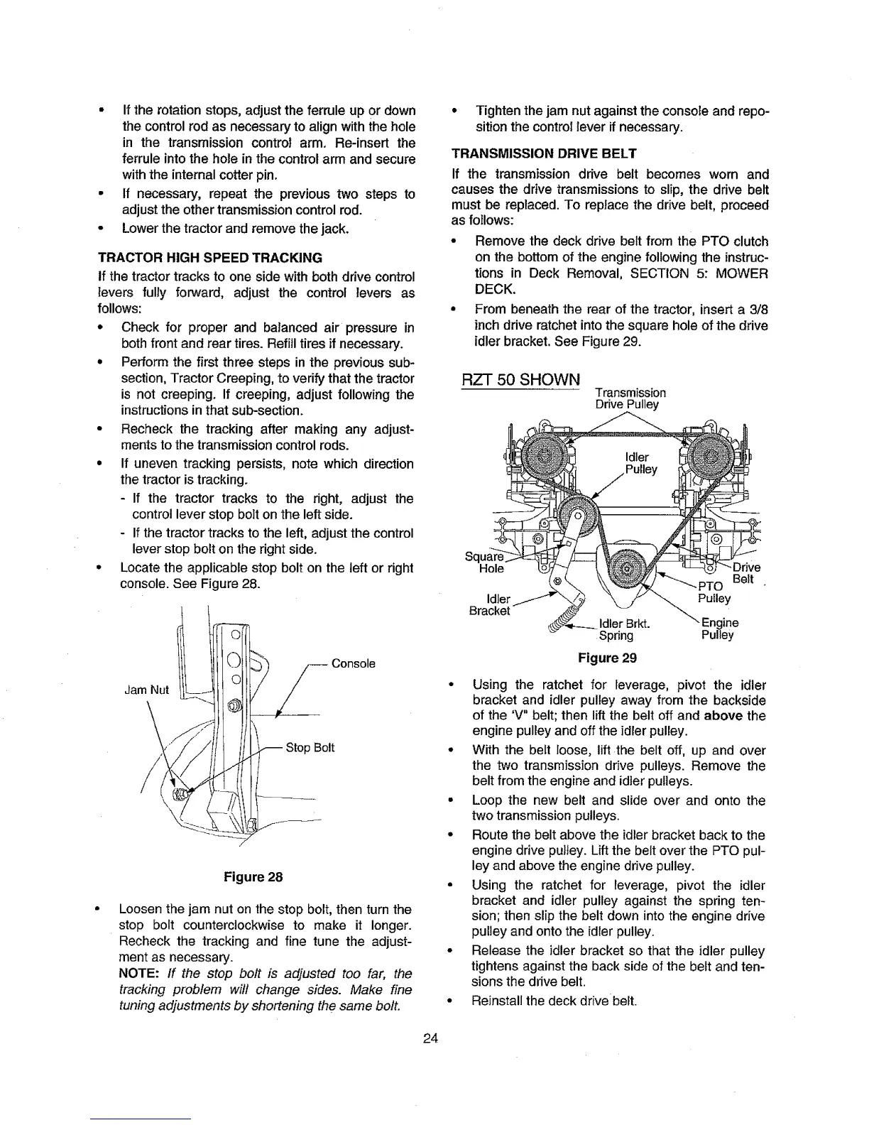
• From beneath the rear of the tractor, insert a 3/8
inch drive ratchet into the square hole of the drive
idler bracket, See Figure 29.
RZT 50 SHOWN
Transmission
DrivePulley
Sq
Hole
Belt
Idler Pulley
Bracket
Idler Brkt. ine
Spring Pulley
Figure 29
• Using the ratchet for leverage, pivot the idler
bracket and idler pulley away from the backside
of the 'V" belt; then lift the belt off and above the
engine pulley and off the idler pulley.
• With the belt loose, lift the belt off, up and over
the two transmission drive pulleys. Remove the
belt from the engine and idier pulleys.
• Loop the new belt and slide over and onto the
two transmission pulleys.
• Route the belt above the idlerbracket back to the
engine drive pulley. Lift the belt over the PTO pul-
ley and above theengine drive pulley.
• Using the ratchet for leverage, pivot the idler
bracket and idler pulley against the spring ten-
sion; then slip the belt down intothe engine drive
pulley and onto the idler pulley.
• Release the idler bracket so that the idler pulley
tightens against the back side ofthe beltand ten-
sions the drive belt.
• Reinstallthe deck drive belt.
24
 Loading...