POSITION DRIVE CONTROL LEVERS
The ddve control levers of the tractor are lowered for
shipping purposes. To accomplish this, the flange lock
nut, hex screw, and flat washer normally usedto secure
each control lever to its pivot bracket are removed. The
hardware is then installedin the slotted hole of each
control lever for shipment. The control levers must be
moved to their operating position. To reposition the con-
trol levers for operation, proceed as follows:
- Remove the hex screw, flat washer, and flange lock
nutfrom the slot of one of the drive control levers.
- Lift and swing that controt lever upward until the
slotted hole in the lever bracket aligns with one of
the holes in the pivot bracket. Refer to Figure 2.
• Slide the fiat washer onto the hex screw. From the
outside, insertthe hex screw w/washer through the
control lever slot and the hole of the pivot bracket.
Secure with the flange rock nut. See Figure 2.
Flange Lock Nut
\ Lever
.Liftcontrol
upward
Fiat Washer
"x_*_--Hex Screw
Bracket
Slotted
Hole
Figure 2
° Note the relative position of the control lever to the
pivot bracket, then repeat the previous steps to
reposition the other control fever in approximately
the same position.
° Refer to "Adjusting the Drive Control Levers" in
Section 3 for instructions on final adjustment of the
levers.
CONNECT THE BATTERY
WARNING: Battery posts, terminals and
related accessories contain lead and lead
compounds. Wash hands after handling.
The tractor is shipped with an activated sealed battery,
with the positive battery cable factory connected. The
negative cable must be connected.
Note: Make sure the ignition switch is in the "OFF" po-
sition before attaching the battery cable.
.
,
Pull the protective cap, if present, off the negative
terminal of the battery, and remove the hex cap
screw and nut from the free end of the negative bat-
terycable.
Connect the negative battery cable (heavy black)
to negative terminal (NEG) of the battery using the
hex cap screw and nut. Slide the black terminal
cover over the negative terminal of the battery.
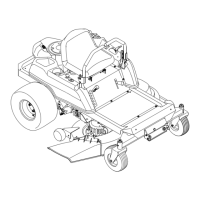
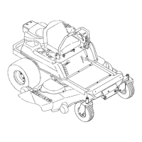
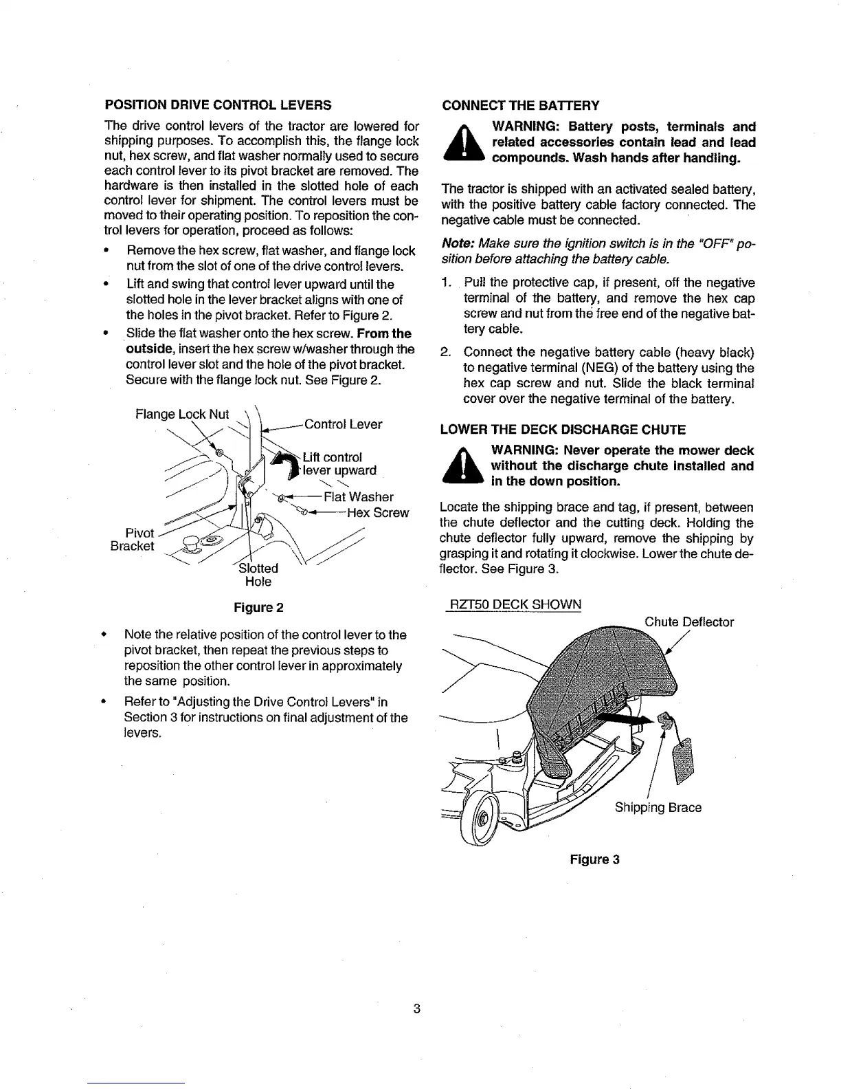
LOWER THE DECK DISCHARGE CHUTE
WARNING: Never operate the mower deck
without the discharge chute installed and
in the down position,
Locate the shipping brace and tag, if present, between
the chute deflector and the cutting deck. Holding the
chute deflector fully upward, remove the shipping by
grasping it and rotating it clockwise. Lower the chute de-
flector. See Figure 3.
RZT50 DECK SHOWN
Chute Deflector
Shipping Brace
Figure 3
3
 Loading...