Hydraulic System 1
31
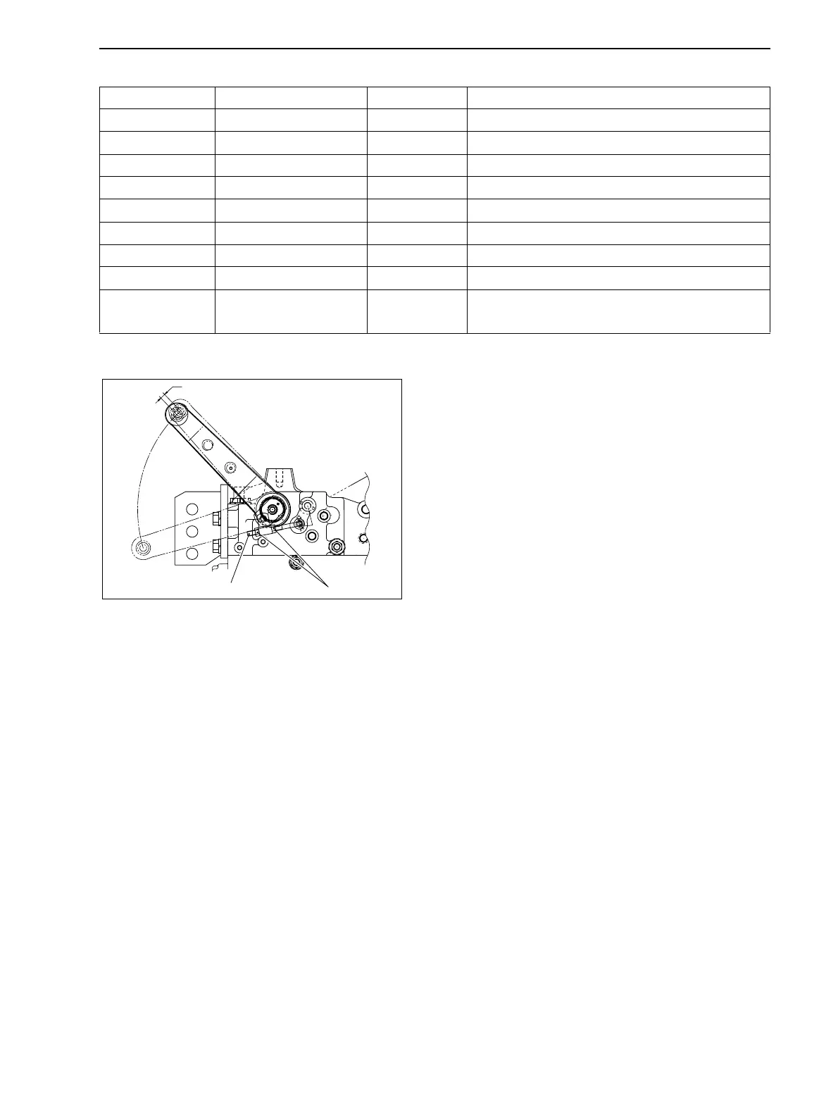
7 Adjustment of Position Control Lever
Adjust the nut for adjuster to stop the lift arm at 5 to
15mm {0.197 to 0.591in} before at the tip of the lift arm
from the upper limit position.
No. Parts Size Torque (N•m {kgf•cm, lbf•ft})
1 Pump mounting nut M8 × 1.25 24.5 to 29.4 {250 to 300, 18.1 to 21.7}
2, 3 Pump mounting nut M6 × 1.0 7.9 to 9.8 {80 to 100, 5.79 to 7.23}
4, 5 Union bolt M16 × 1.5 39 to 44 {400 to 450, 28.9 to 32.5}
6 Union bolt G1/2 58.8 to 68.6 {600 to 700, 43.4 to 50.6}
7, 8, 9 Adaptor G1/4 39 to 49 {400 to 500, 28.9 to 36.2}
10, 11 Union G3/8 49 to 59 {500 to 600, 36.2 to 43.4}
12, 13, 14 Elbow 90° G3/8 39 to 44.1 {400 to 450, 28.9 to 32.5}
15, 16 Hose joint G1/4 25 {260, 18.8}
10, 11, 12, 13 Bite type joint ø 15
Temp. tightening 44 to 59 {450 to 600, 32.5 to 43.4}
Tightening 59 to 69 {600-700, 43.4 to 50.6}
7
Adjuster
Nut
5 to 10mm {0.197 to 0.591in}
GZ3W31-031
www.mymowerparts.com
K&T Saw Shop 606-678-9623 or 606-561-4983
 Loading...