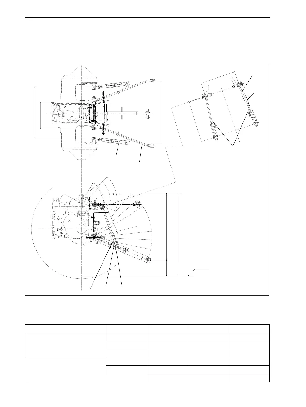
4 Dimension
20
Mounting Procedure for Three-Point Link
When mounting the implement to the 3-point link, set it the most appropriate position in accordance with the
implement.
Range Adjustment of the Length for Lift Rod and Top Link
Road Clearance at Lower Link Hitch Point
(Unit : mm {in})
Model Lift Rod Lower Hole Center Hole Upper Hole
7530
F: 7 - 14 (ø 740 {ø 29.1})
R: 9.5 - 24 ( ø 1100 {ø 43.3})
Upper Limit 769 {30.3} 845 {33.3} 915 {36.0}
Lower Limit 184 {7.2} 295 {11.6} 401 {15.8}
Range of Lift 586 {23.1} 550 {21.7} 513 {20.2}
7532
F: 25 × 8.50 - 14 (ø 635 {ø 25.0})
R: 13.6 - 16 (ø 982 {ø 38.7 })
Upper Limit 713 {28.1} 789 {31.1} 859 {33.8}
Lower Limit 128 {5.0} 239 {9.4} 345 {13.6}
Range of Lift 586 {23.1} 550 {21.7} 513 {20.2}
Liftrod
Locknut
Turnbuckle
Lowerlink
Upperhole
Centerhole
Lowerhole
Ground
Rangeoflift
Lower
limit
Upperlimit
Stabilizer
Liftrod
Mountingwidth
(387{15.2})
460{18.1}
(44.5)
(R230{9.06})
(61.1
)
(293{11.5})
(567{22.3})
(R261.14{10.281})
(R635.58{25.023})
682{26.9}
mm{in}
GZ3W10-004
www.mymowerparts.com
K&T Saw Shop 606-678-9623 or 606-561-4983
 Loading...