Domestic Series 7000 Hydraulics
12
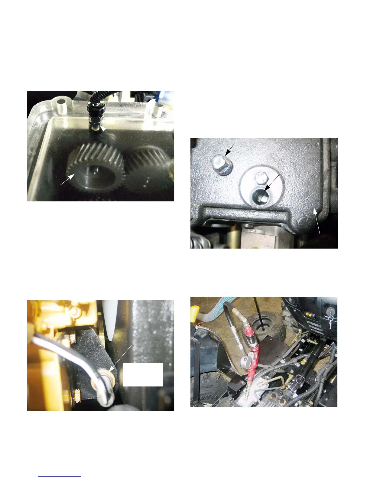
6.7. If the tractor has a speed sensor mounted in the
transmission cover, it is a hall effect device that
employs the auxiliary pump drive gear as a tone-
ring to generate a tachometer signal. This was
done on early (2003 production) tractors.
See Figure 6.7.
6.8. On tractors with the transmission mounted
speed sensor, if the tachometer works, the pump
drive is confirmed to be working as well.
6.9. The speed sensor is visible without removing the
fenders. It is located on the transmission cover,
directly above the auxiliary pump.
6.10. Current production uses an engine-mounted
speed sensor, or an ignition generated tachome-
ter signal on gasoline engines. See Figure 6.10.
6.11. The rear fenders must be removed to access the
auxiliary pump itself. Fender removal is detailed
in the 2003 Cub Cadet Technical Handbook on
pages 6-21 through 6-27.
6.12. If the tractor has an engine mounted speed sen-
sor, the pump drive can be inspected with a
flashlight and probe.
6.13. Remove the pipe plug that fills the hole previ-
ously used for the speed sensor.
6.14. The auxiliary pump drive gear should be visible
through the hole. See Figure 6.14.
6.15. To test the auxiliary pump that powers the steer-
ing and lift cylinder, use a flow and pressure
gauge set. See Figure 6.15.
NOTE: Equipment will vary from shop to shop,
but operating principles are similar.
Figure 6.7
Auxiliary pump
drive gear
Eary style
speed sensor
NOTE: see-through
transmission coverissi
Figure 6.10
Engine
mounted
speed sensor
(front of
crankshaft on
CAT engine)
Figure 6.14
Transmission
cover
Plug (removed)
Auxilieary pump
drive gear (visible
through port)
Figure 6.15

 Loading...