Domestic Series 7000 Hydraulics
2
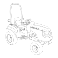
1.7. The steering pump, located in the dash pedestal
contains it’s own back-up gerotor charge pump
that will enable steering control when the engine
is not running. See Figure 1.7.
1.8. The steering pump directs fluid pressure to one
end of the double-acting differential steering cyl-
inder while allowing it to return from the other
end of the cylinder in order to provide steering
action.
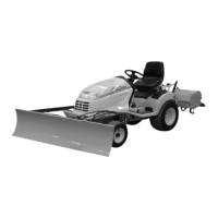
1.9. The lift cylinder is operated by a control valve
and feedback rod under the right rear fender.
See Figure 1.9.
1.10. The control valve directs fluid pressure to a sin-
gle-acting hydraulic cylinder that lifts the three-
point lift arms.
1.11. The hydraulic fluid flow is as follows:
1.12. Through the pick-up tube from the transmission
sump and filter, to the auxiliary pump.
See Figure 1.12.
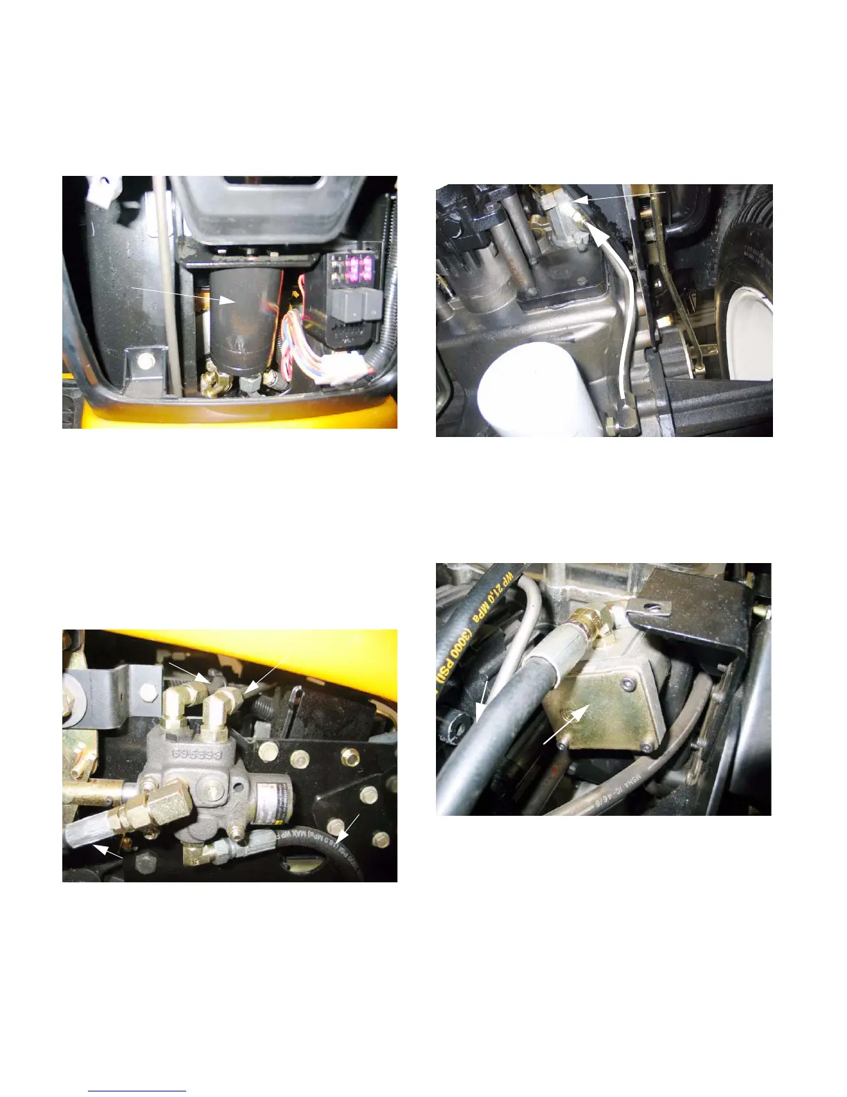
1.13. Under pressure from the auxiliary pump the fluid
goes to the steering pump, connecting to the “P”
port on Sauer steering pumps. On Ross steer-
ing pumps, it connects to the “IN” port.
Figure 1.7
Steering
pump
Figure 1.9
From Steering
unit
To lift cylinder
To return manifold
Direct return
Figure 1.12
Auxiliary pump
Filter
Flow
Figure 1.13
Auxiliary pump
(steering and
lift cylinder)
Line to
steering
unit
 Loading...