21
01021076
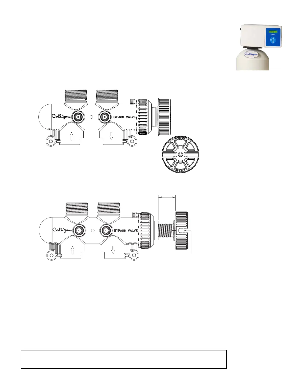
(see directional arrow on the end of knob) until the knob stops as shown. DO NOT OVERTIGHTEN!
(Figure 16)
Figure 15. Turn blue bypass knob clockwise.
About 1-1/4”
A screwdriver shank may be
used in the slot as a lever for
extra turning force if needed.
Figure 16. Turn bypass knob counter-clockwise.
Drain Line Connection
Refer to Table 3 for drain line length and height limitations under the applicable tank size.
1. Remove 1/2” pipe clamp from the small parts pack included with the control.
2. Route a length of 1/2” drain line from the drain elbow to the drain.
3. Fasten the drain line to the elbow with the clamp.
4. Secure the drain line to prevent its movement during regeneration. When discharging into a
sink, or open floor drain, a loop in the end of the tube will keep it filled with water and will
reduce splashing at the beginning of each regeneration.
NOTE Waste connections or drain outlets shall be designed and constructed to
provide for connection to the sanitary waste system through an air gap of
two pipe diameters or 1 inch, whichever is larger.