22
01021076
NOTE Note: Observe all plumbing codes. Most codes require an anti-siphon device
or air gap at the discharge point. The system and installation must comply
with state and local laws and regulations.
Operating
Pressure
0 ft (0 m) 2 ft (0.6 m) 4 ft (1.2 m) 6 ft (1.8 m) 8 ft (2.4 m) 10 ft (3 m)
30 psi (210 kPa) 60 ft (18 m) 50 ft (15 m) 30 ft (9 m) 15 ft (5 m) Not allowable Not allowable
40 psi (279 kPa) 100 ft (30 m) 90 ft (27 m) 70 ft (21 m) 50 ft (15 m) 30 ft (9 m) 12 ft (4 m)
50 psi (349 kPa) 145 ft (41 m) 115 ft (35 m) 80 ft (24 m) 80 ft (24 m) 60 ft (18 m) 40 ft (12 m)
60 psi (419 kPa) 100 ft (30 m) 100 ft (30 m) 85 ft (26 m) 60 ft (18 m)
80 psi (559 kPa) Normal installation should not require 140 ft (43 m) 120 ft (37 m)
100 psi (699 kPa) more than 100 ft (30 m) of drain line 150 ft (46 m)
Table 3. Height of Discharge Above Floor Level Operating.
Connect the Brine Line
1. Measure a length of brine line suf-
ficient to reach from the brine tank
to the brine fitting, with no sharp
bends. For easier access to the float
it is recommended to add an extra
four feet (1.3 meters) of length to the
brine line.
2. Cut both ends of the brine line
squarely and cleanly.
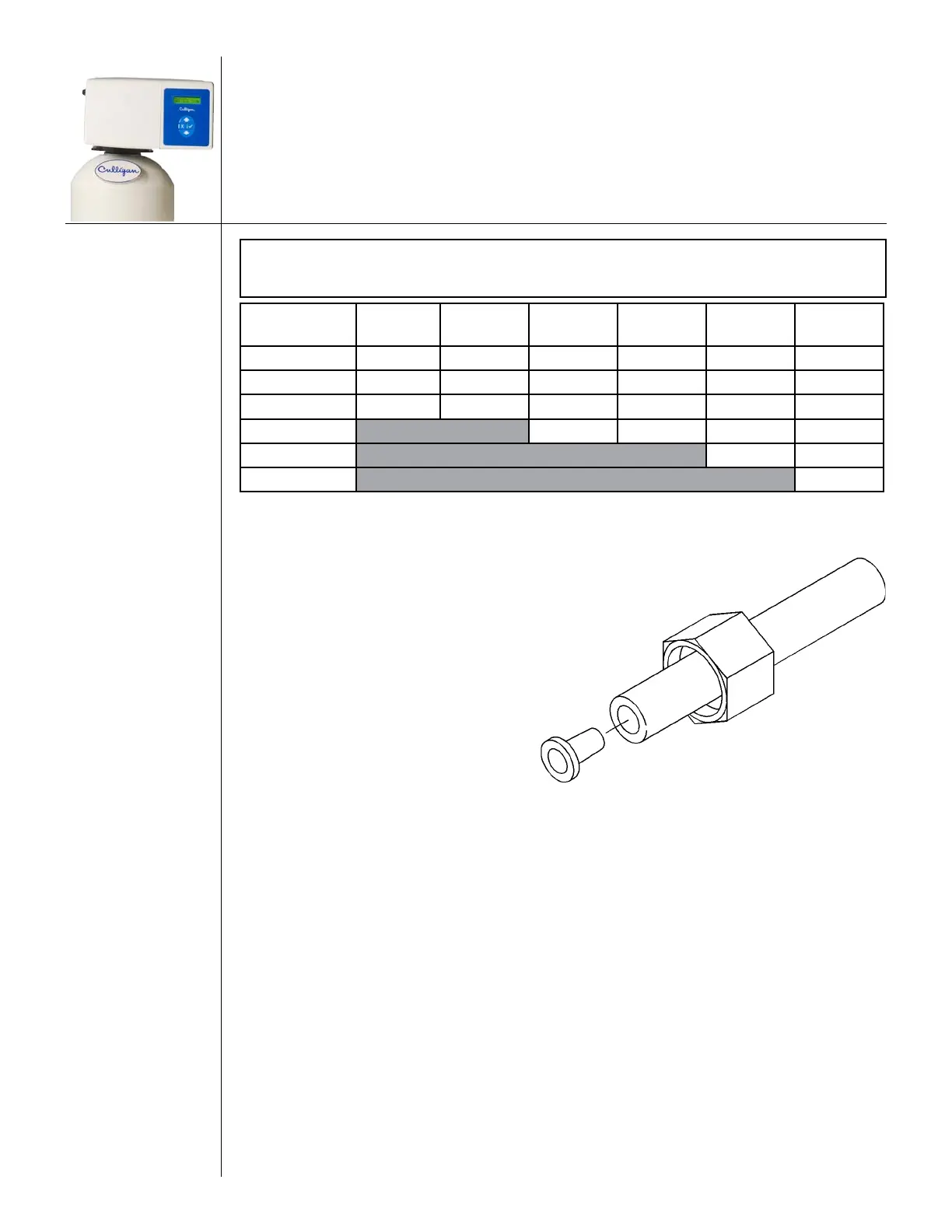
3. Slip the white nut over one end of
the tubing and press the plastic insert
into the end of the tubing (Figure
17). Connect to the brine valve and
tighten nut.
4. Remove white nut and plastic insert from the small parts pack.
5. Slip the white nut over one end of the tubing and press the plastic insert into the end of the tub-
ing (Figure 17). Connect to the brine connection on the valve and tighten nut.
Fill The Salt Storage Container
Fill the salt storage container with water until the level reaches about 1 inch above the salt support plate.
Pour salt into the container. Fill with salt to within a few inches of the top.
Figure 17. Brine valve tubing.