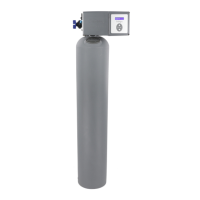
26 Culligan® High Efficiency 1.5 Water Filter
26 Cat. No. 01024514
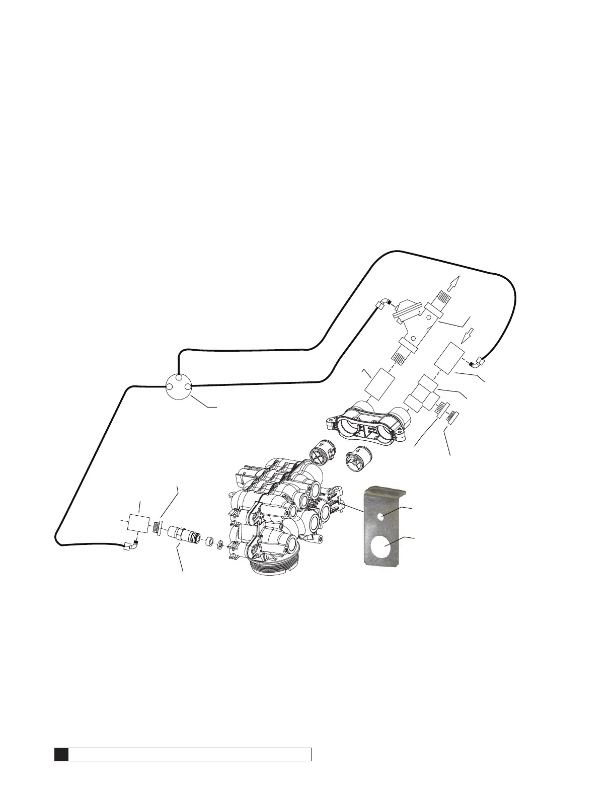
Installing the Blocking Solenoid Valve
1. Mount the solenoid valve securely to the valve using bracket (P/N 01025234).
2. Remove the conduit nut from the valve.
3. Insert the wires through the opening.
4. Secure the valve to the cover using the conduit nut.
5. Attach the end connector on the solenoid valve wiring to the Aux 4 output connector on the GBE auxiliary board.
6. Connect the diaphragm valve to the outlet side of the valve using a 1-1/2” coupling (not supplied) and connect
the tubing as shown in Figure 30. We recommend that the pressurized water source is from a soft water supply.
7. Run the solenoid exhaust line to a suitable drain.
3
2
1
Figure 30. Suggested piping and tubing for multi-tank systems.
*Not supplied
1/8”NPT x
1/4” Tube Elbow*
Drain Fitting
1/8”NPT x 1/4” Tube Elbow*
To Siphon
Break
1” Coupling*
1”X1/2” Reducing Bushing*
3/4” Vacuum
Breaker*
1-1/2” x 3/4”
Reducing
Bushing*
Blocking Solenoid Valve
(P/N 01016331)
1-1/2” Tee*
1-1/2” Coupling W/Tap*
1-1/2”
Coupling*
1/8”NPT x
1/4” Tube Elbow*
Inlet
1-1/2”
Diaphragm
Valve
(P/N 00445981)
Attach Bracket to Valve
Attach the Blocking Solenoid Valve
to the Bracket