Installing Accessories 27
Cat. No. 01024514
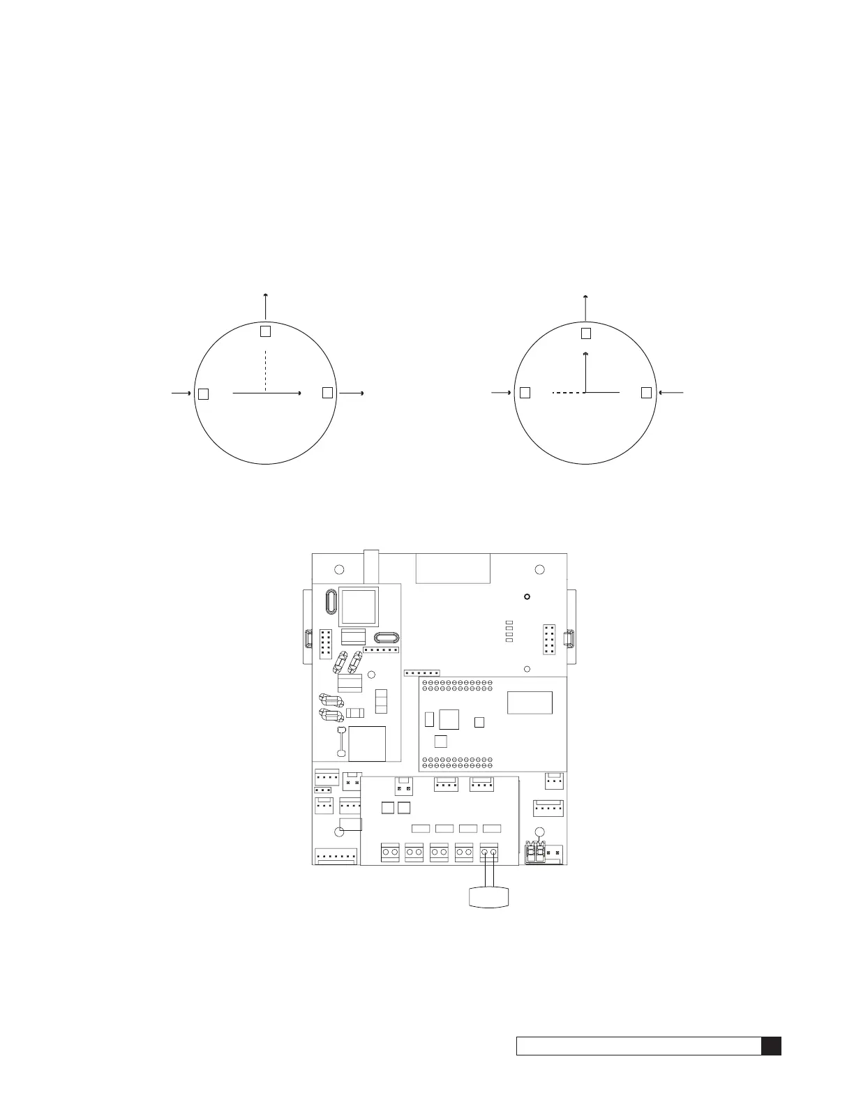
Sequence of Operation
When a filter is in standby or a regeneration cycle, the GBE controller sends a signal to the Aux 4 terminal of the primary
auxiliary board (see Figure 32), activating the solenoid valve. When the solenoid valve is electrically activated, ports #1
and #2 of the solenoid (Figure 31) become common. This will direct pressure from a constant IN pressure supply to the
blocking diaphragm valve, which prohibits the flow of water to service. Once the controller signals the unit to return to a
Service status, the solenoid valve is deactivated. When the solenoid valve is electrically deactivated, ports #1 and #3 of
the solenoid become common. This will vent pressure, from the diaphragm valve to drain. The diaphragm valve opens to
allow treated water to flow to service.
3
2
1
To Drain
Blocking
Diaphragm
Solenoid Valve Energized
When Tank
in Regen or Standby
N/C
N/O
N/O
2
3
1
To Drain
From
Pressurized
Source
From Blocking
Diaphragm Valve
Solenoid Valve Not Energized
When Tank "Online"
Solenoid Valve
N/C
N/O
N/O
Solenoid Valve
From
Pressurized
Source
Figure 31.
SOL
PHONE
24v
2.5v
Figure 32.