9
CONDUIT CENTERLINE BENDING RADII
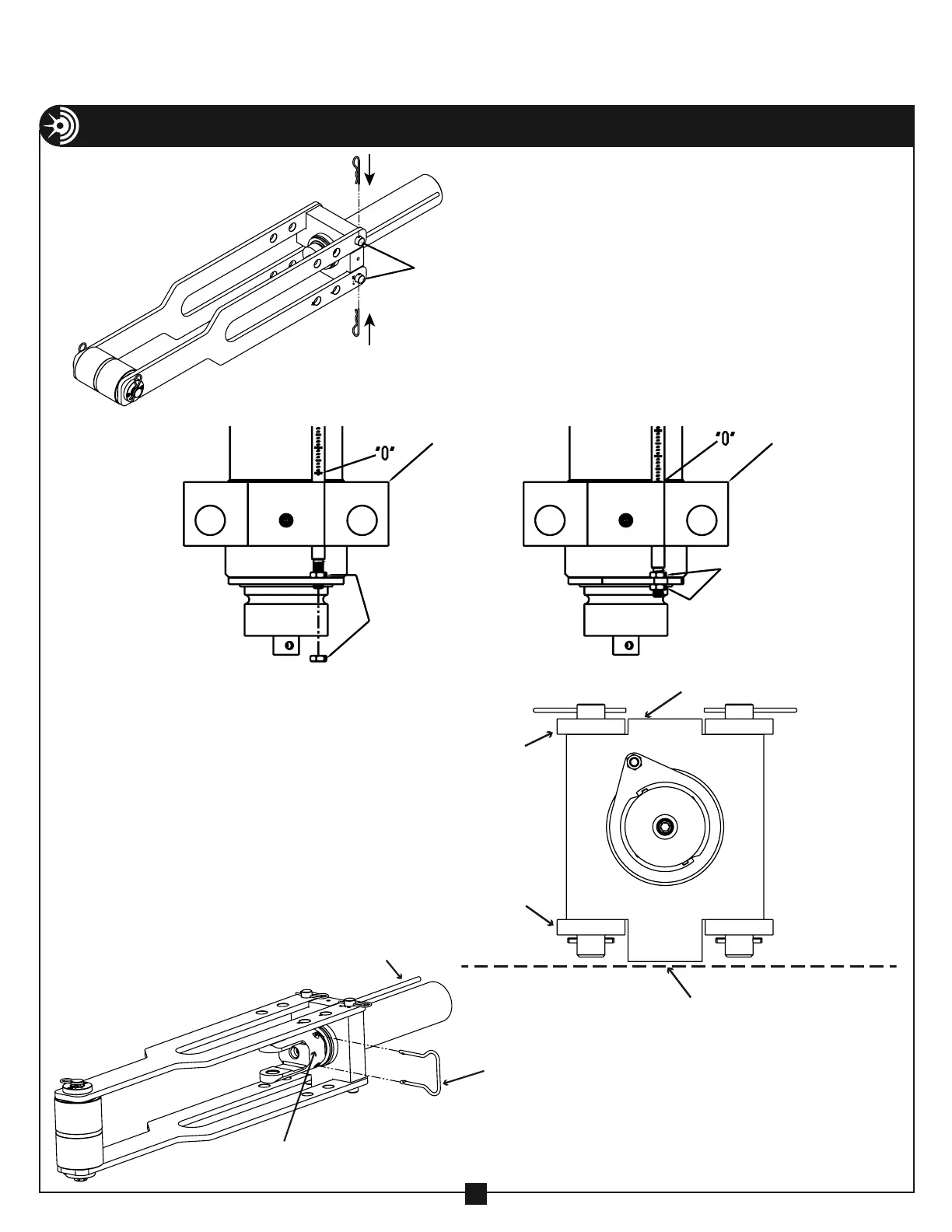
ASSEMBLY & OPERATING INSTRUCTIONS – 254 CONDUIT BENDER
(CONTINUED)
5. Adjust gauge rod such that gauge reads
zero when the cylinder is fully retracted.
NOTE: To adjust gauge rod, loosen
gauge rod adjusting nuts (see Figure
9A) and adjust rod such that zero (ø) is
flush with the top of the cylinder block
(see Figure 9B).
4. Place the hydraulic cylinder with the cylinder
mounting block between the frame sides as
shown in Figure 9. Insert the two cylinder
block pins into the appropriate frame side
holes for the size of conduit to be bent and
secure each with a spring clip.
NOTE: The hydraulic cylinder with mounting
block in Figure 9 is shown pinned in the
position for bending 4" conduit. The frame
side holes are marked to indicate where to
pin the mounting block for each size.
FIGURE 9
6. Rotate the frame and hydraulic
cylinder so the long side of the
cylinder mounting block is resting
on the floor (See Figure 9C). Then
place the clevis onto the end of the
hydraulic cylinder and secure with the
clevis retaining clip (see Figure 9D).
GAUGE ROD
CLEVIS
RETAINING
CLIP
CLEVIS
FIGURE 9C
SHORT SIDE OF THE
CYLINDER MOUNTING BLOCK
FRAME SIDE
FRAME SIDE
LONG SIDE OF THE
CYLINDER MOUNTING BLOCK
FLOOR
FIGURE 9D
CYLINDER
BLOCK
CYLINDE
BLOCK
ADJUSTING
NUTS
ADJUSTING
NUTS
CYLINDER
BLOCK PINS
FIGURE 9B
FIGURE 9A