10
CONDUIT CENTERLINE BENDING RADII
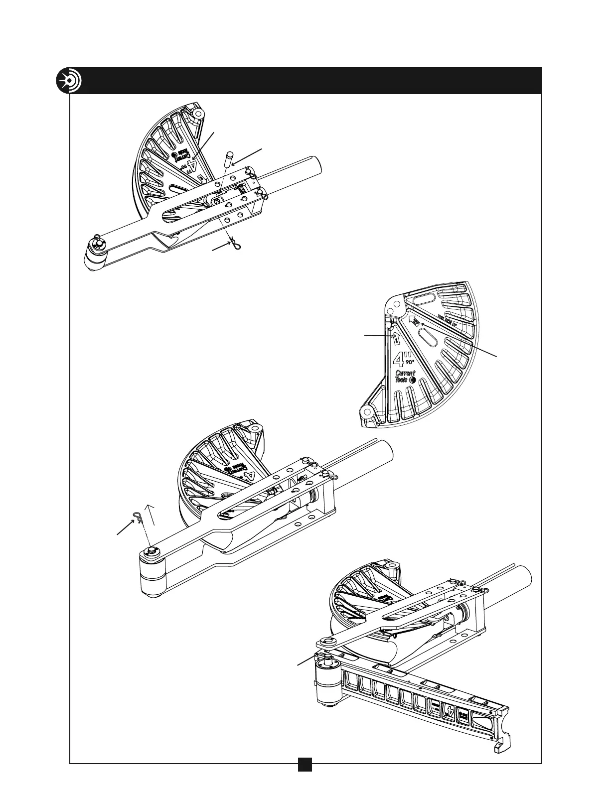
ASSEMBLY & OPERATING INSTRUCTIONS – 254 CONDUIT BENDER
(CONTINUED)
7. Select the shoe for the size conduit
you will be bending. Place the shoe
between the frame sides as shown,
with the conduit size facing upward.
Align the clevis with the correct hole
on the shoe for the type conduit you
will be bending (Rigid/IMC or EMT).
Insert the clevis pin and secure with
a spring clip (see Figure 10).
NOTE: Arrows on the bending shoe
indicate the correct hole for bending
either Rigid/IMC or EMT conduit (see
Figure 10A).
CLEVIS PIN
SPRING CLIP
CONDUIT SIZE
8. Remove the spring clip from
the roller assembly as shown
in Figure 10B.
SPRING CLIP
9. Raise the frame side and place
the correct follow bar for the
size conduit to be bent
between the frame sides as
shown in Figure 10C. The
“START” mark on the follow bar
should be just past the roller
assembly and face upward.
FIGURE 10
FIGURE 10A
FIGURE 10B
FIGURE 10C
RIGID/IMC
EMT
“START”
MARK ON
FOLLOW BAR