10
2
3
5
11
8
13
6
6
1
1
1
1
4
7
9
5
5
2
2
12
Figure 2
Figure 3
Figure 4
Figure 5
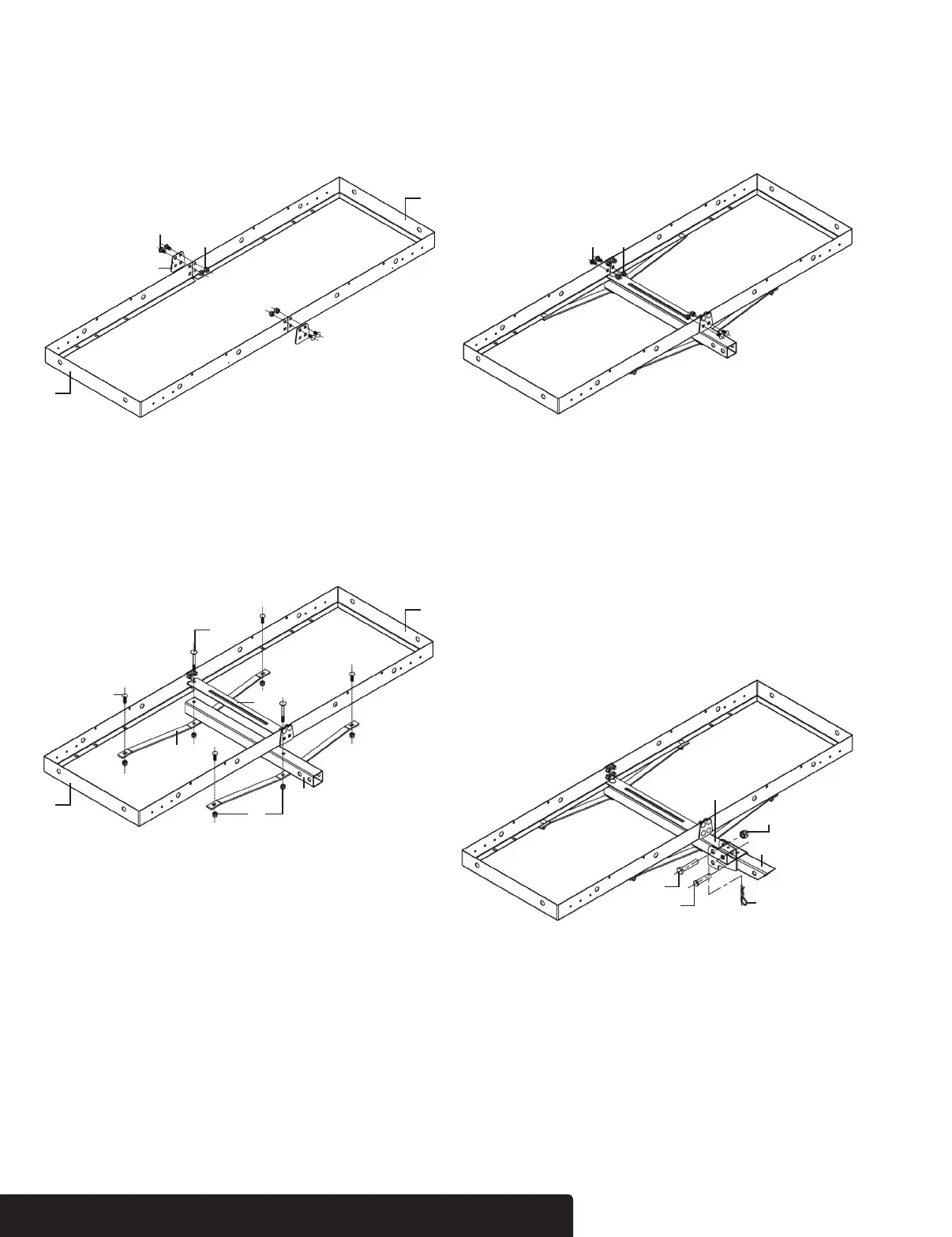
AssemBlY
Step 1
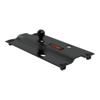
Align the two platform halves (#1), as shown below. Using
the top two holes only, connect the platform halves (#1) and
connecting plates (#13) with M10*20 carriage bolts (#2) and
M10 locknuts (#5). Tighten to 80% only.
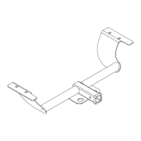
Step 2
Put the 2" shank (#6) under the middle of platform (#1). Place
the support bridge (#7) under the 2" shank (#6). Place the flat
brace (#3) in the top middle of the platform (#1). Connect by
tightening the M10*80 carriage bolt (#4) and M10 locknut (#5)
to 80% tightness.
Step 4
Using the bottom two holes, finish connecting the platform
halves (#1) and connecting plates (#13) with M10*20 carriage
bolts (#2) and M10 locknuts (#5). Tighten to 80% only.
Step 5
Fully tighten all of the bolts and locknuts.
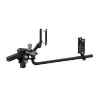
Step 6
Insert the 2" shank (#6) into the foldable connection bar (#9).
Align all of the holes. Insert the M16*80 hex head bolt (#8)
through the hole closeest to the cargo carrier and secure
with M16 locknut (#12). The pin (#11) should be inserted in
the hole closest to the vehicle. To fold the basket, remove
pin (#11), fold basket up, and place pin (#11) in the lower
hole. The clip (#10) must always be attached to the pin.
cuRtmFG.com • NEED ASSISTANCE? • 1.800.798.0813 • 18109-INS-RA • PAGE 2