2 — INSTALLATION AND WIRING
1212 & 1212P Manual - Sep 2019
Return to TOC
pg. 6
WIRING: STANDARD INSTALLATION, 1212
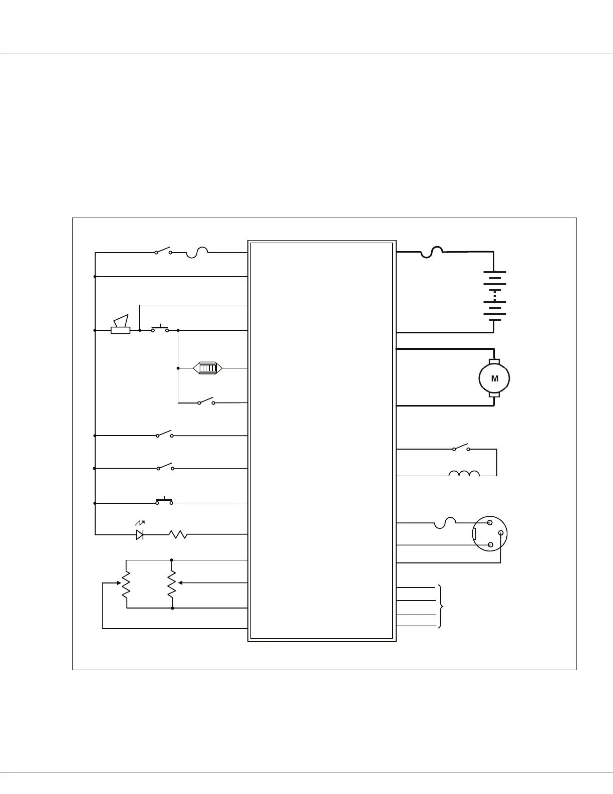
e wiring diagram presented in Figure 3a shows a typical installation for a DME application. is
installation is shown with a single-ended 3-wire 5kΩ potentiometer throttle and a reverse switch.
With wigwag throttles, a reverse switch is not used and Pin J1-12 is le unconnected.
e optional speed inhibit input can be wired into the circuit in various ways; in the standard
installation shown here, it is B- active (Inhibit Type parameter set to 0).
e J2 connector can be used interchangeably for the programmer or for the battery charger.
Figure 3a
Standard Wiring Configuration, Curtis 1212 Controller.
SPEED INHIBIT
KEYSWITCH
CONTROL
FUSE
M2
M1
J1-8
J3-1
B-
B+
POWER
FUSE
BATTERY
Programmer
1212 Controller
MODE (M1,M2)
J1-4
J1-2
J1-1
J1-6
J2-4
J2-3
J2-2
J2-1
B+
I/O GND
Tx
Rx
MOTOR
J1-5
KSI
MODE SW
STATUS LED
REVERSE
PUSH
PUSH SW
J1-14
HORN
I/O GND
POT WIPER
J1-3
J1-11
BDI(0-5V)
J3-2
BRAKE +
BRAKE -
EM BRAKE
J1-9
B+
B-
CHARGE INHIBIT
J2-3
CHARGER
SOCKET
J1-10
POT HIGH
J1-7
B+
POT LOW
HORN SW
STATUS LED
R
HORN
INHIBIT SW
J2-4
J2-2
B+
I/O GND
BRAKE SW(optional)
J1-12
REVERSE SW
J1-13
5KΩ
THROTTLE
POT
100kΩ
SPEED
POT
SPEED LIMIT POT