2 — INSTALLATION AND WIRING
1212 & 1212P Manual - Sep 2019
Return to TOC
pg. 4
2 — INSTALLATION AND WIRING
MOUNTING THE CONTROLLER
e 1212/1212P controller can be oriented in any position, but the location should be carefully
chosen to keep the controller clean and dry. If a clean, dry mounting location cannot be found,
a cover must be used to shield the controller from water and contaminants.
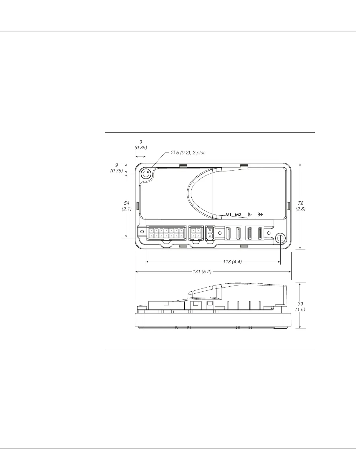
e outline and mounting hole dimensions are shown in Figure 2. e controller should be mounted
by means of the two mounting holes at the opposing corners of the heatsink, using M4 (#8) screws.
Figure 2
Mounting
Dimensions,
Curtis 1212
and 1212P
Controllers.
Dimensions in millimeters and (inches)
You will need to take steps during the design and development of your end product to ensure that its
EMC performance complies with applicable regulations; suggestions are presented in Appendix A.