2 — INSTALLATION AND WIRING
1212 & 1212P Manual - Sep 2019
Return to TOC
pg. 8
THROTTLE WIRING
Either a 3-wire potentiometer throttle or a voltage throttle can be used with the 1212/1212P controller.
e controller can accept a single-ended, inverse single-ended, wigwag, inverse wigwag, or unipolar
input signal from the throttle, depending on how the rottle Type parameter is programmed; see
page 18.
rottle wiring is described in the following text. If the throttle you are planning to use is not covered,
contact the Curtis office nearest you.
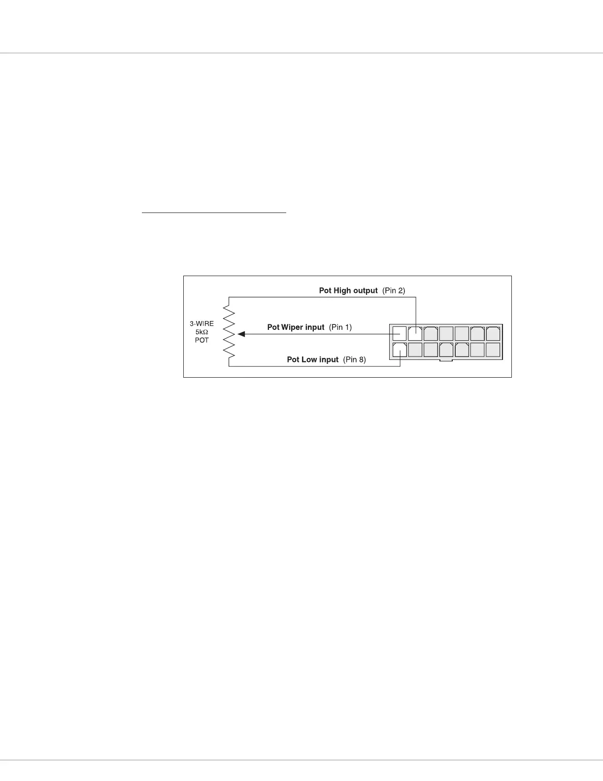
5kΩ, 3-Wire Potentiometer
A 5kΩ, 3-wire potentiometer is shown in the wiring diagrams (Figures 3a and 3b) as well as in
Figure 4. With this throttle, the controller can be programmed for a rottle Type 0–4 input signal;
see page 18.
1234567
8910 11 12 13 14
Figure 4
Wiring for 3-Wire,
5K
Ω
Potentiometer
rottle.
For wigwag, inverted wigwag, and unipolar applications, the pot can be correctly centered within the
controller’s neutral band by using the throttle autocalibration feature (see page 20).
e controller provides full pot fault protection against open or shorted wires anywhere in the
throttle assembly. e overall pot resistance should be 4.3 to 7.0 kΩ. Values outside this range will
trigger a fault condition. If a pot fault occurs while the vehicle is moving, the controller will decelerate
the vehicle to a smooth stop using the decel rate set by the Key O Decel parameter. If the fault is
corrected while the throttle is still applied, an HPD fault will be issued and driving is disabled until
throttle is reduced to neutral.