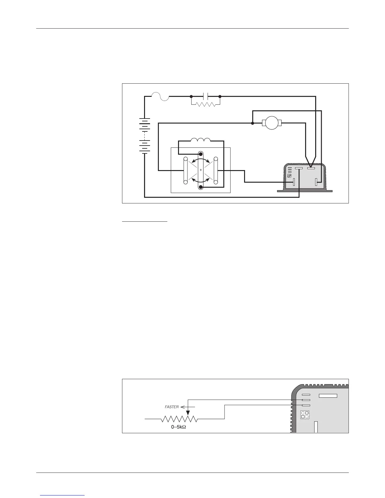
Wiring for mechanical reversing switch (golf car type)
As shown in Figure 7, this type of switch mechanically interchanges the two
motor field cables by rotating a movable contact bar. The configuration shown
is typical; many variations are in use.
Throttle Wiring
Ten throttle types can be used with these controllers:
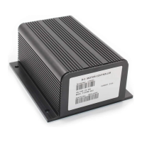
Type 0 2-wire potentiometer, 0–5kΩ
Type 1 2-wire potentiometer, 5kΩ–0
Type 2 single-ended 0–5V input
Type 3 2-wire potentiometer, 4.6kΩ–0
Type 4 2-wire potentiometer, 5.5kΩ–0
Type 5 2-wire potentiometer, 1kΩ–0
Type 6 ITS input
Type 7 single-ended 6.3–10.6 V input
Type 8 single-ended 6–12 V input
Type 9 single-ended 3-wire potentiometer, 0–5kΩ
Throttle Type 0
Wiring for Type 0 throttles is simple: just connect the two wires to the J2 and J3
push-on terminals; it doesn’t matter which wire goes on which terminal. With
Type 0 throttles, resistance increases as the applied throttle is increased.
Fig. 7 Wiring for reversing
with a mechanical F/R
switch arm.
A2
M–
B– B+
+
–
PRECHARGE RESISTOR
(250 �, 5 W)
FUSE
S2
S1
A2
A1
MOTOR ARMATURE
MOTOR FIELD
Mechanical potboxes and footpedals are Type 0 throttles. It doesn’t matter which
wire goes on which terminal, and the wires can be extended as required.
Fig. 8 Wiring for Type 0
throttles.
J1
J2
J3
2 — INSTALLATION & WIRING: Throttle Wiring
10
Curtis 1204M/1205M/1209M/1221M Manual