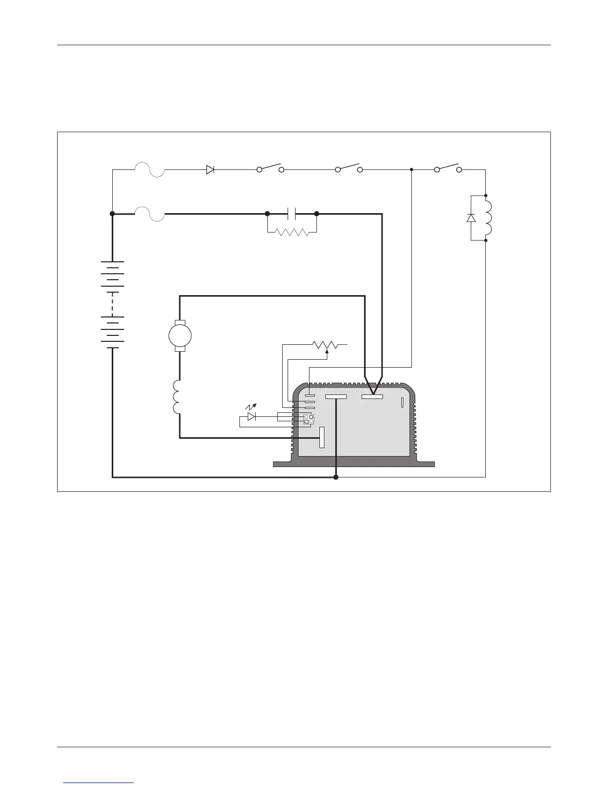
Basic Wiring Conguration for Pump Applications
The 1204M-6302 controller has only three busbars; it is appropriate for use
with pump motors, wired as shown in Figure 11.
2 — INSTALLATION & WIRING: Throttle Wiring; Pump Applications
Fig. 11 Basic wiring diagram, Curtis 1204M-6302 motor controller—for pump applications.
STATUS
LED
MOTOR
FIELD
A2
5k� THROTTLE
PRECHARGE RESISTOR
(250 � , 5 W)
MOTOR
ARMATURE
MAIN
MAIN
KEYSWITCH INTERLOCKS
POLARITY
PROTECTION
DIODE
FUSE
POWER WIRING
FUSE
S1
+
–
ENABLE
A1
S2
M–
B– B+
J1
J2
J3
J4
J5
14
Curtis 1204M/1205M/1209M/1221M Manual