STEERING AND SUSPENSION
Page P-3
Repair and Service Manual
Read all of Section B and this section before attempting any procedure. Pay particular attention to all Notes, Cautions and Warnings
Install wheel/tire assembly and check for smooth rotation
of the wheel and an absence of play when the wheel is
grasped by the outside of the tire.
Fork Bearing Inspection
Tool List Qty. Required
Floor jack .................................................................... 1
Jack stands ................................................................. 2
Wheel chocks.............................................................. 4
Grease .................................................................... A/R
Wrench, 15/16" ........................................................... 1
Wrench, 1 1/2" ............................................................ 1
Lift the front of the vehicle and support on jack stands as
shown in Section B (Safety). Grasp the lower fork and
rock it. If any movement is detected, the fork bearing may
require replacement/adjustment.
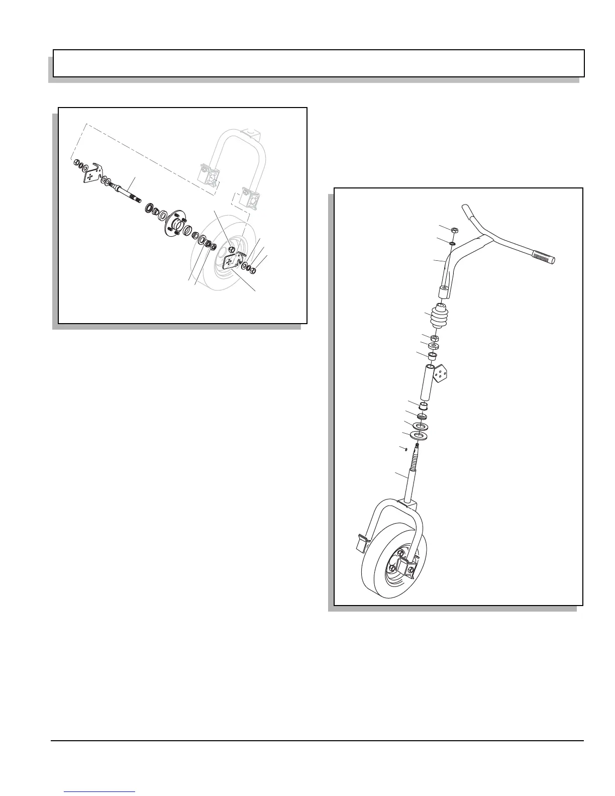
Remove the nut (item 1), washer (item 2), boot (item 3)
and handlebar (item 4). Remove the jam nut (item 5),
spindle nut (item 6) and remove fork assembly (item 7).
The bushings (item 8) may now be removed. Inspect the
fork assembly shaft (item 7) and the bushings (item 8) for
excessive wear and replace if required (Ref Fig. 5 on
page P-3).
Inspect the V ring (item 9), Thrust washer (item 10) and
rubber washer (item 11) for wear or deterioration and
replace if required.
Installation is the reverse order of disassembly. Tighten
the spindle nut (item 6) until the fork assembly (item 7)
moves freely but without vertical motion. Tighten the jam
nut (item 5) firmly and confirm that the adjustment is still
satisfactory.
Install the woodruff key (item 12) and position boot (item
3) over nuts. Locate handlebar (item 4) over woodruff key
and secure with nut item (item 1). Tighten firmly.
Fig. 4 Front Wheel and Bearing Installation
3
2
5
8
4
Part of Front
Fork Assembl
7
6
1
Fig. 5 Fork, Hub and Handlebar Components
1
2
3
12
5
9
4
10
11
8
8
6
7