GENERAL INFORMATION & ROUTINE MAINTENANCE
Page A-7
Repair and Service Manual
Read all of Section B and this section before attempting any procedure. Pay particular attention to all Notes, Cautions and Warnings
Handlebar Installation
If the handlebar is factory installed,
make sure the retaining nut is tight.
Otherwise install the fork spindle key, handle, lockwasher and
nut. Tighten the nut to 50 ft. lbs. (68 Nm) torque.
Failure to install the fork
spindle key and to tight-
en the handlebar retain-
ing nut may allow the handlebar to come loose,
resulting in loss of vehicle steering control.
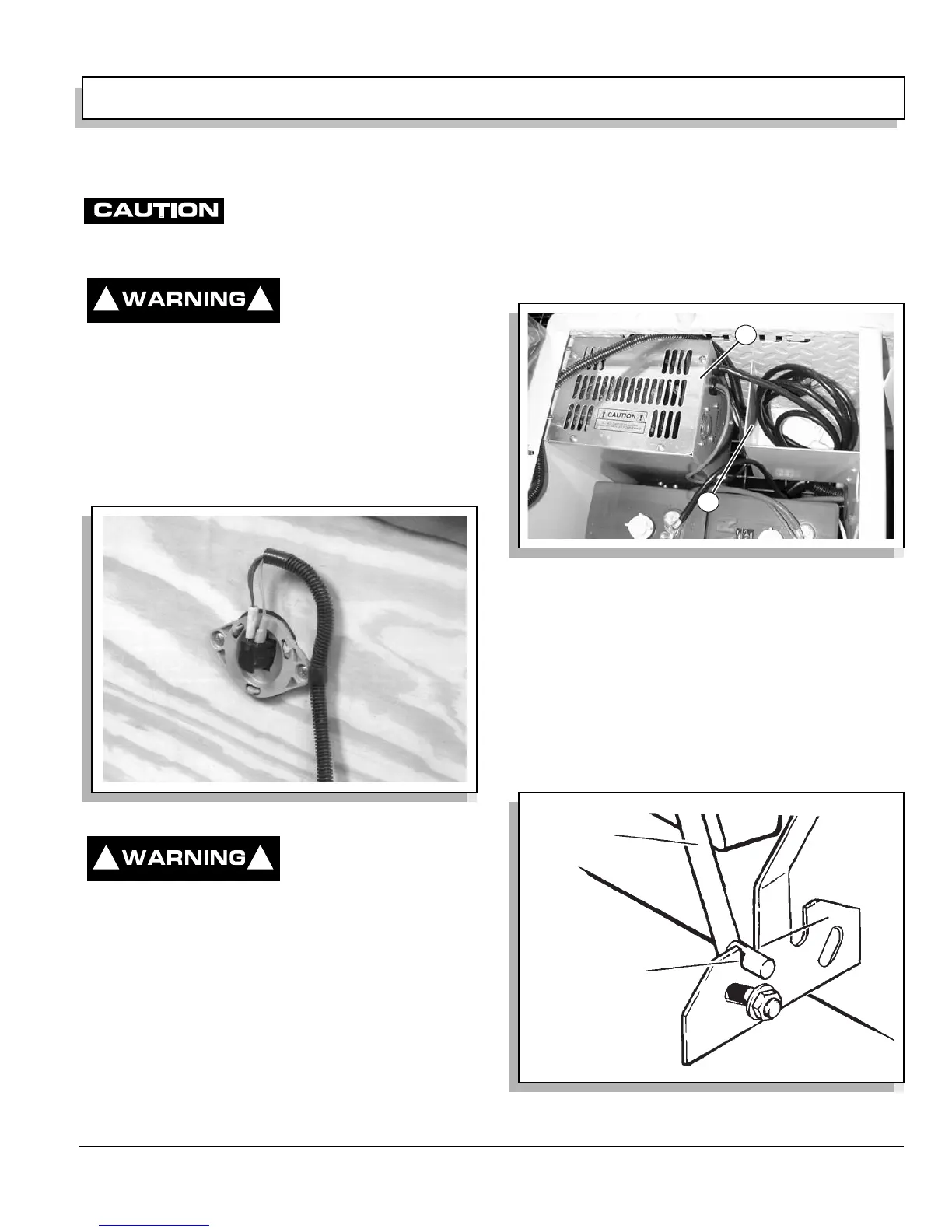
Seat Switch
The seat switch, located under the operator’s seat,
allows the vehicle to function only when the seat is in
position and the operator is properly seated. Should the
operator leave the seat during operation, the vehicle will
stop (Ref Fig. 15 on page A-7).
To prevent unexpected
vehicle movement, NEV-
ER operate the vehicle if
the seat switch is malfunctioning.
Hour Meter (Accessory)
The hour meter, located in the motor compartment,
behind the speed controller, records the number of hours
the vehicle has been operated.
ADDITIONAL FEATURES
Additional features include a built-in battery charger, a
fold down backrest and a programmable speed control-
ler.
Battery Charger
The standard vehicle is equipped with a built-in 24 volt,
25 amp DC, 120 volt AC, 60 Hz, fully automatic charger,
located under the driver’s seat. There is also a storage
area under the seat for the charger cord (Ref Fig. 16 on
page A-7).
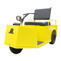
Fold Down Backrest
The backrest is easily positioned to provide seating for a
passenger or, in a raised position, for cargo.
To lower the backrest, lift it upward and toward the front
of the vehicle. When the pins on either side have cleared
the slots, slowly lower the backrest into position. Reverse
the procedure when raising the backrest (Ref Fig. 17 on
page A-7).
Fig. 15 Seat Switch
! !
! !
Fig. 16 Battery Charger
Fig. 17 Fold Down Backrest
2
1
COMBINATION
BACKREST
AND SEAT
SLOT
PIN