BRAKES
Page J-4
Repair and Service Manual
Read all of Section B and this section before attempting any procedure. Pay particular attention to all Notes, Cautions and Warnings
the braking surface.
It is recommended that a suitable greaseless type sol-
vent be used to clean the braking surface of brake drums
before they are placed in service to assure the cleanest
possible surface.
Brake Shoe Removal
Tool List Qty. Required
Hydraulic floor jack...................................................... 1
Jack stands ................................................................. 4
Chocks ........................................................................ 4
Plastic faced hammer.................................................. 1
Pliers ........................................................................... 1
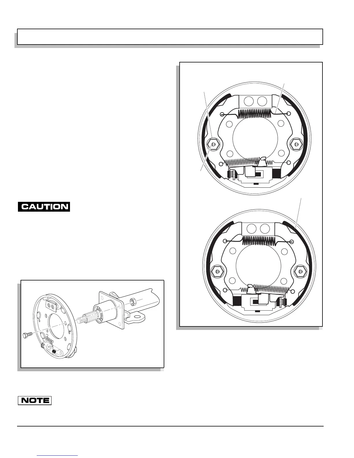
Using a pair of pliers, compress the brake shoe spring
retainer (1) at the open end of spring (Ref Fig. 4 on page
J-4). While holding the tension pin (2) with the pliers, turn
the retainer spring 1/4 turn to align the slot in the spring
retainer with the flats on the tension spring.
Do not turn the pins as their seal
may be broken.
Remove the brake shoe retainer springs.
Grasp the brake shoes (3) in the center and tilt them out-
ward and away from the back mounting plate. This will
release the tension on the heavy shoe springs (4).
Remove the brake springs and remove the brake
shoes.Brake shoe installation is the reverse of removal
procedure.
The brake manufacturer recommends to
replace all springs, pins and retainer when new
brake shoe is installed.
Brake Removal
Tool List Qty. Required
Hydraulic floor jack ......................................................1
Jack stands..................................................................4
Chocks.........................................................................4
Ratchet, 1/2” drive .......................................................1
Socket, 1/2” .................................................................1
Retaining ring puller.....................................................1
Fig. 5 Backing Plate Removal and Installation
Fig. 4 Brake Shoes and Springs
4
Heavy Shoe Spring
3
Brake Shoe
Retainer Ring
2
Tension Pin
1