ELECTRICAL SYSTEM AND BATTERY CHARGER
Page H-2
Repair and Service Manual
Read all of Section B and this section before attempting any procedure. Pay particular attention to all Notes, Cautions and Warnings
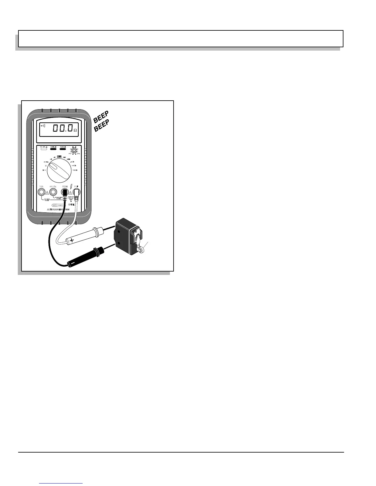
Testing a Switch for Continuity
Place one probe on one contact of the switch, place the
second probe on the second terminal of the switch (Ref
Fig. 2 on page H-2).
Actuating a normally open (NO) switch will cause the
DVOM to show ‘0’ or give an audible indication when the
switch is operated. A normally closed (NC) switch will
cause the meter to show ‘0’ or give an audible indication
when the probes are attached without activating switch.
The audible indicator will stop and the meter display will
indicate a value greater than ‘0’ when the switch is acti-
vated.
The change in display or audible indicator demonstrates
that the switch is functioning.
Refer to wiring diagram set DVOM to DC Volts attach
negative (-) probe to battery post indicated. Follow steps
shown on wiring diagram and test for battery voltage at
location indicated.
Fig. 2 Continuity Check of Switch
Press to
activate
switch