I.B. 29C891B
Page 5
Effective 11/98
The following would be used:
• OPTIM 550 (if field IMPACC kit installed)
• OPTIM 750 and/or 1050 Trip Units
• Digitrip RMS 810 and/or 910 Trip Units
• Other IMPACC Compatible devices
• One or more OPTIMizer Hand Held Programmers
• One or more assembly/remotely mounted Breaker
Interface Modules
• IMPACC software/central PC
Refer to Figure 1-9 for typical system configurations uti-
lizing the OPTIM Trip Unit System and other compatible
devices. For additional IMPACC details, refer to Section
3 of Instruction Book 29C890.
1-4 FEATURES AND FUNCTIONS
Digitrip OPTIM 550, 750 and 1050 Trip Units provide a
wide range of common protection and coordination fea-
tures and functions. The Digitrip OPTIM 1050 Trip Unit
also provides power quality and energy monitoring capa-
bilities.
1-4.1 COMMON FEATURES OF DIGITRIP OPTIM
550, 750 AND 1050 TRIP UNITS
Precise system coordination is provided by an expan-
sive number of time-current curve shaping adjustments.
This is accomplished by the large number of incremen-
tal setpoints available for both current pickup and time
settings.
Programmable Protection and Coordination
Adjustments
• Long delay setting
• Long delay time with selectable I
2
t or I
4
t slopes
• Short delay setting
• Short delay time with selectable flat or I
2
t slopes
• Instantaneous setting
• Ground fault setting
• Ground fault time with selectable flat or I
2
t slopes
The trip units also have a selectable powered and
unpowered thermal memory to provide protection
against cumulative overheating should a number of
overload conditions occur in quick succession.
The trip unit information system utilizes LEDs to indicate
the trip mode following an automatic trip operation. The
LEDs are complemented by trip event information that is
stored in non-volatile memory after a trip condition. This
trip information can then be accessed via the Optimizer
Hand Held Programmer, the Breaker Interface Module,
or over the IMPACC System.
Selectable early warning alarms, such as the high load
current alarm, are capable of being indicated locally and
remotely. They are provided to help keep a system
operating and productive.
System Monitoring
All OPTIM Trip Units are capable of monitoring the fol-
lowing data:
• Steady-State value of phase and neutral or ground
currents
➀
• Minimum and maximum current values
• Average demand current
• Cause of trip
• Magnitude of fault current responsible for an automat-
ic trip operation
➀
LSI version of OPTIM 550 only monitors phase
currents
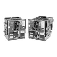
Figure 1-8 Monitor and Control from Central PC