I.B. 29C891B
Page 22
Effective 11/98
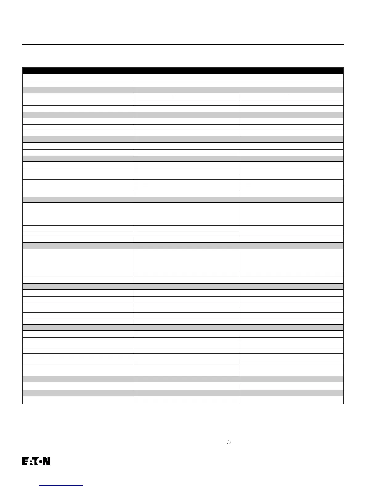
TRIP UNIT TYPE DIGITRIP OPTIM 550
RMS Sensing Yes
Programmable Yes
CIRCUIT BREAKERS
Types Series C K, L and N-Frames Series C R-Frames
Ampere Range 70 - 1200A 800 - 2500A
Interrupting Rating @ 480V 30 thru 100KA 65 thru 100KA
TRIP UNIT ORDERING OPTIONS
LSI
➀➁ Yes Yes
LSIG
➀➁ Yes Yes
LSIA (Remote over IMPACC only) Yes Yes
PROTECTION AND COORDINATION
Interchangeable Rating Plug (I
n
) 70-1200A 800-2500A
Over-Temperature Trip Yes Yes
LONG DELAY PROTECTION
Long Delay Setting (I
r
) ➂ 0.4 - 1.0 x I
n
(0.01 steps) 0.4 - 1.0 x I
n
(0.01 steps)
Long Delay Pickup 116% of I
r
116% of I
r
Long Delay Time I
2
t @ 6 x I
r
➃ 2-24 secs (0.10 steps) 2-24 secs (0.10 steps)
Long Delay Time I
4
t @ 6 x I
r
(SDT Slope Flat only) ➄ 1-5 secs (0.10 steps) 1-5 secs (0.10 steps)
Long Delay Thermal Memory (Powered or Unpowered) Yes (programmable) Yes (programmable)
High Load Alarm 0.5 - 1.0 x I
r
0.5 - 1.0 x I
r
SHORT DELAY PROTECTION
Short Delay Pickup ➂ 1.5 - 8.0 x I
r
(0.1 steps) 1.5 - 8.0 x I
r
(0.1 steps)
Short Delay Time I
2
t @ 8 x I
r
➅ 0.1 - 0.5 secs (0.01 steps) 0.1 - 0.5 secs (0.01 steps)
Short Delay Time Flat
➅ 0.1 - 0.5 secs (0.01 steps) 0.1 - 0.5 secs (0.01 steps)
Zone Selective Interlocking No No
INSTANTANEOUS PROTECTION
Instantaneous Pickup
➆ 2.0 - 8.0 x I
n
(0.1 steps) 2.0 - 10.0 x I
n
(0.1 steps)
(1600 & 2000A)
2.0 - 6.0 x I
n
(0.1 steps)
(2500A)
Discriminator Yes Yes
Override (Fixed Instantaneous)
➇ Yes Yes
GROUND FAULT PROTECTION
Ground Fault Alarm (not to exceed 1200A) ➈ 0.2 - 1.0 x I
s
(0.01 steps) 0.24 - 1.0 x I
n
(0.01 steps)
Ground Fault Pickup (not to exceed 1200A)
➆ 0.2 - 1.0 x I
s
(0.01 steps) 0.24 - 1.0 x I
n
(0.01 steps)
Ground Fault Delay I
2
t @ 0.62 x I
n
/I
s
➉ 0.1 - 0.5 secs (0.01 steps) 0.1 - 0.5 secs (0.01 steps)
Ground Fault Delay Flat 0.1 - 0.5 secs (0.01 steps) 0.1 - 0.5 secs (0.01 steps)
Zone Selective Interlocking No No
Ground Fault Memory Yes Yes
SYSTEM MONITORING
Digital Display Yes (Using OPT) Yes (Using OPT)
Current Yes Yes
Cause of Trip LEDs Yes Yes
Magnitude of Trip Information Yes Yes
Remote Signal Contacts No No
Power and Energy No No
Power Quality - Harmonics No No
Power Factor No No
COMMUNICATIONS
IMPACC Field Upgradeable Field Upgradeable
TESTING
Testing Method OPT, BIM, IMPACC OPT, BIM, IMPACC
➀ No ground fault alarm (A) provided
➁ Refer to para. 3-2.3 and Figure 3-4 for details
➂ Setting Tolerance ±5%
➃ Setting Tolerance +0-30%
➄ Setting Tolerance +10-40%
Notes:
I
n
= Rating Plug
I
r
= Long Delay Setting
I
s
= Sensor Rating
OPT = Hand Held Programmer (OPTIMizer)
BIM = Breaker Interface Module
➅ Setting Tolerance (See time-current curves)
➆ Setting Tolerance ±10%
➇ Setting Tolerance ±20%
➈ Only available with LSIA
➉ I
s
(K, L & N-Frame), I
n
(R-Frame, SPB)
Contact factory or Vista for K-Frame availability
Table 3.2 Digitrip OPTIM 550 Trip Unit System Capabilities Overview
11
 Loading...