I.B. 29C891B
Page 26
Effective 11/98
• Ground Fault
- Ground Fault Pickup
- Ground Fault Delay, Flat Response
- Ground Fault Delay, I
2
t Response
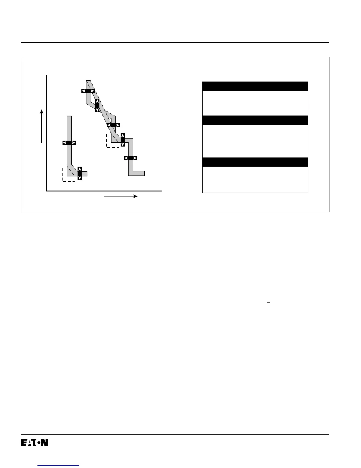
The ten curve shaping possibilities are illustrated in
Figure 3-5. Each portion of the curve is discussed and
illustrated individually in the following paragraphs (3-2.4,
3-2.5, 3-2.6 and 3-2.7).
Notice: For the sake of simplification, many curve illus-
trations in this section will be represented as
single line curves. Keep in mind, however, that
a time-current curve in reality is represented by
a band of minimum and maximum values, not
a single line (Figures 3-1 and 3-5).
3-2.4 LONG DELAY PROTECTION
All Digitrip OPTIM Trip Units provide programmable long
delay protection consisting of (Tables 3.2 and 3.3 and
Figure 3-4):
• Long delay current setting
• Long delay time setting
• Long delay thermal memory
Figure 3-5 Typical OPTIM Trip Unit Time-Current Curve (10 Curve Shaping Adjustments)
OVERLOAD AND SHORT CIRCUIT
1. Long Delay Setting
2A. Long Delay Time I
2
t
2B. Long Delay Time I
4
t
SHORT CIRCUIT
3. Short Delay Pickup
4A. Short Delay Time Flat Response
4B. Short Delay Time I
2
t Response
5. Instantaneous
GROUND FAULT
6. Ground Fault Pickup
7A. Ground Fault Delay Flat Response
7B. Ground Fault Delay I
2
t Response
• High load alarm (in software with IMPACC, and dis-
creet contact on R, SPB and DSII breakers)
Long Delay Current Setting (I
r
)
The long delay current setting (I
r
) is established as a
multiple of the rating plug value (I
n
). The programmable
range is as follows:
• 0.4 to 1.0 times (I
n
) in 0.01 increments
Example: A 600 ampere Series C L-Frame circuit break-
er with a 400 ampere rating plug installed and
the long delay current setting programmed to
160 amperes results in a 40% setting.
The long delay current setting (I
r
) for OPTIM Trip Units
is the nominal continuous current rating of the breaker.
The breaker will carry this maximum amount of current
(I
r
) continuously without tripping. It is not the actual
long delay pickup point. The breaker will pickup and
ultimately trip at a current level that is nominally higher
than the Long Delay Current Setting (I
r
):
•
For DSII/DSLII, Long Delay Pickup is calibrated for
nominally 105% (Ir)
•
For K, L, N and R-Frames and SPB, the calibration is
for nominally 116% (I
r
)