I.B. 29C891B
Page 8
Effective 11/98
SECTION 2: HARDWARE DESCRIPTION
AND EQUIPMENT INTERFACES
2-1 GENERAL
The purpose of this section is to familiarize the reader
with Digitrip OPTIM Trip Units, their nomenclature, the
way trip units are interfaced with specific equipment,
and trip unit specifications. The information presented is
divided into the following four parts:
• General Trip Unit Details
• Trip Units By Type
• Trip Unit Accessories
• Specification Summary
2-2 GENERAL TRIP UNIT DETAILS
This section describes general trip unit functioning, trip
unit hardware, circuit breaker specific details, and
required interfaces with other external equipment.
2-2.1 TRIP UNIT CONFIGURATION
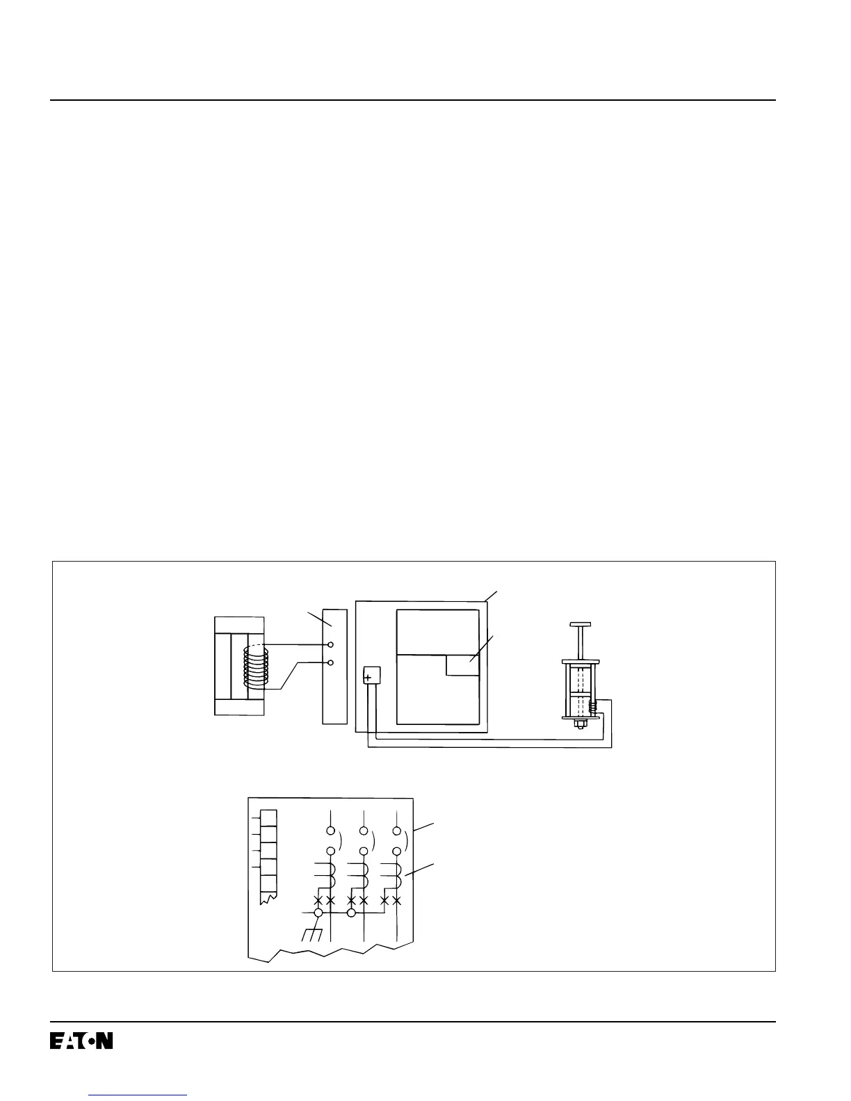
A complete OPTIM Trip Unit System consists of current
sensors, electronic circuitry and a flux transfer shunt trip
device contained inside the circuit breaker (Figure 2-1).
The trip units are completely self-contained and, when the
circuit breaker is closed, no external power is required to
operate their protective systems. They operate from cur-
rent signal levels and control power is derived from the
current sensors integrally mounted in the circuit breakers.
Circuit protection is achieved by analyzing the sec-
ondary current signals received from the circuit breaker
current sensors. As signals are received and analyzed,
a trip signal to the flux transfer shunt trip is initiated
when programmed current levels and time delay set-
tings are exceeded.
2-3 TRIP UNIT PACKAGES
The features associated with the three different OPTIM
Trip Unit models (550, 750 and 1050) are outlined in
Figure 1-5.
Figure 2-1 Typical OPTIM Trip Unit Circuitry (DSII Type Circuit Breaker Shown)
 Loading...