I.B. 29C891B
Page 10
Effective 11/98
Notice: Trip unit should be powered from an external
control power source. If control power is not
available the LEDs will temporatily operate off
the battery. Refer to the wiring diagrams list-
ed in Appendix A, Table A.1 for control power
connections.
Battery for Trip Indicators
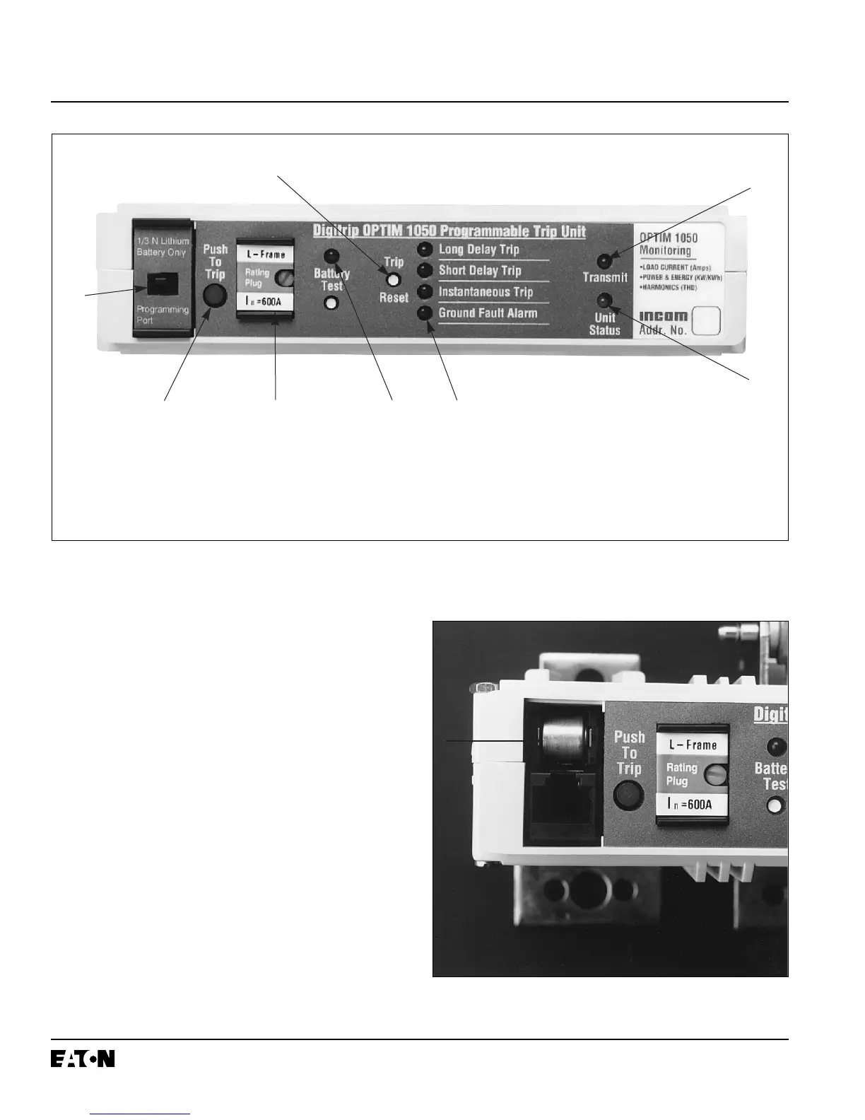
A replaceable 3 volt lithium battery is located behind a
small access cover on the left side of the trip unit
(Figure 2-5). A test pushbutton and LED test indicator
are also provided. The test pushbutton will energize the
LED indicator if the battery is in good working condition.
Refer to paragraph 5-4.1 for battery replacement infor-
mation.
Trip Indicator Reset Pushbutton
A trip reset pushbutton is provided to turn off a mode of
trip LED indicator after an automatic trip. The reset
pushbutton is located next to the four mode of trip led
indicators.
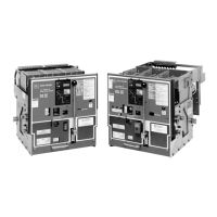
Figure 2-4 Front View of L-Frame Type OPTIM Trip Unit (K and N-Frame Designs are Similar)
Figure 2-5 K, L and N-Frame Type OPTIM Trip Unit
Battery Compartment
➅
➀ Push-to-Trip Button
➁ Mode of Trip/Alarm LEDs
➂ Battery Test Pushbutton/LED
➃ Automatic Trip Indicator Reset
Pushbutton
➄ Unit Status LED
➅ INCOM Transmit LED (Model 550 requires field IMPACC kit)
➆ Battery Compartment/Pro-gramming Port Access Cover
➇ Rating Plug
➄
➆
➀
➃
➇ ➂
➁
 Loading...