I.B. 29C891B
Page 27
Effective 11/98
Long delay pickup, which is determined from the time-
current curves, establishes the current level at which the
trip unit’s long time tripping function begins timing. If after
a programmed amount of time the current condition still
exists, the trip unit’s tripping system is enabled.
Alarm indicators are provided as follows:
• K, L and N-Frame Breakers
- BIM Contacts
- LED (Long Delay Pickup) flashes on breaker trip unit
- Ground Alarm Contact (optional accessory for 750
and 1050 units)
• R-Frame, SPB and DSII/DSLII Breakers
- BIM Contacts
- LED (Long Delay Pickup) flashes on breaker trip unit
- Discrete Contacts
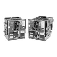
Figure 3-6 graphically illustrates how the long delay set-
ting portion of the overall curve can be moved horizon-
tally and independently by means of the programmable
settings.
Long Delay Time Setting (I
2
t or I
4
t Slopes)
The long delay time setting is established at 6 times the
long delay current setting (6 x I
r
). This is the reference
point where the programmed long delay time setting is
fixed on the time-current curve.
Figure 3-6 Typical Long Delay Setting Adjustment
The long delay time setting is programmable to an I
2
t or
an I
4
t slope over a wide range of times for all OPTIM
Trip Units as follows:
• I
2
t Slope - 2 to 24 seconds in increments of 0.10
secs.
• I
4
t Slope - 1 to 5 seconds in increments of 0.10
secs.
Notice: (1) When an I
4
t slope is programmed for the
long delay time setting, the short delay
time setting must be set to a FLAT slope.
(2) When an I
2
t slope is programmed for the
long delay time setting, the short delay
time setting may be set to FLAT or I
2
t.
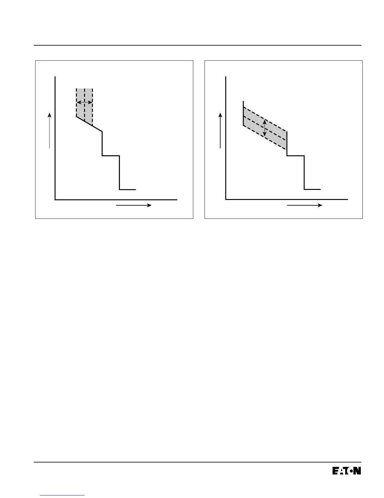
The long delay time setting is used to establish the
amount of time a sustained overload condition will be
carried before the circuit breaker trips. Figures 3-7 and
3-8 graphically illustrate how the long delay time portion
of the overall curve can be moved vertically and inde-
pendently by means of the programmable settings.
Long Delay Thermal Memory
All Digitrip OPTIM Trip Units are provided with a selec-
table (powered or unpowered) thermal memory to pro-
tect against cumulative overheating should a number of
overload conditions occur in quick succession.