Ground fault alarm unit Connections to ground fault alarm Check connections Table A.1
does not operate on a unit are incorrect. Wiring Diagrams
ground fault.
Ground fault alarm is not operating Press test button on ground fault alarm unit. Table A.1
Button should illuminate. If it does not, check Instructions for
that 120V is being supplied to unit. If it is, ground fault alarm
replace the ground fault alarm unit.
Breaker is not providing an alarm Temporarily disconnect the wires to L1 and L2 on Table A.1
signal. the ground fault alarm unit. With these connec- Intstructions for
tions open, approximately 5 volts should appear ground fault alarm
between GF, AL and COM when the ground fault
current exceeds pickup. On ground fault alarm
breakers, this voltage will be present as long as
pickup is exceeded. On ground fault trip break-
ers, this voltage appears only transiently after a
trip and must be observed with an oscilloscope.
If the voltage is not present, the problem may be
in the breaker. Refer to Note 1 at the end of
Table 5.1.
Breaker trips on ground There actually is a ground fault Find the location of the fault and remove it. N.A.
fault.
On four wire systems the neutral (1) Check that the neutral sensor and neutral Table A.1
current sensor may not have the sensor connections on side terminal block are Wiring Diagrams
correct ratio or be properly con- good. (2) Check that the neutral current sensor
nected. ratio matches the breaker. (3) Check that con-
nections from the neutral current sensor to the
breaker are not reversed polarity.
Trip unit may be the problem. Replace breaker. Refer to Note 1 at end of Para. 5-3
Table 5.1
Breaker trips too rapidly GOUT to GIN and/or SOUT to SIN Add connections Table A.1
on ground fault or short are not connected. Wiring Diagrams
delay (zone selective inter-
locking not used). Trip unit settings are not correct Change settings I.B. 29C892, Section 3
or
I.B. 29C893, Section 4
Trip unit may be the problem. Replace breaker. Refer to Note 1 at end of Para. 5-3
Table 5.1
Breaker trips too rapidly Powered thermal memory may If powered thermal memory is not required, I.B. 29C892, Para 3-6
on long delay. cause breaker to trip too soon. turn it off using OPTIMizer.
Trip unit settings are not correct Change settings I.B. 29C892, Section 3
or
I.B. 29C893, Section 4
I.B. 29C891B
Page 45
Effective 11/98
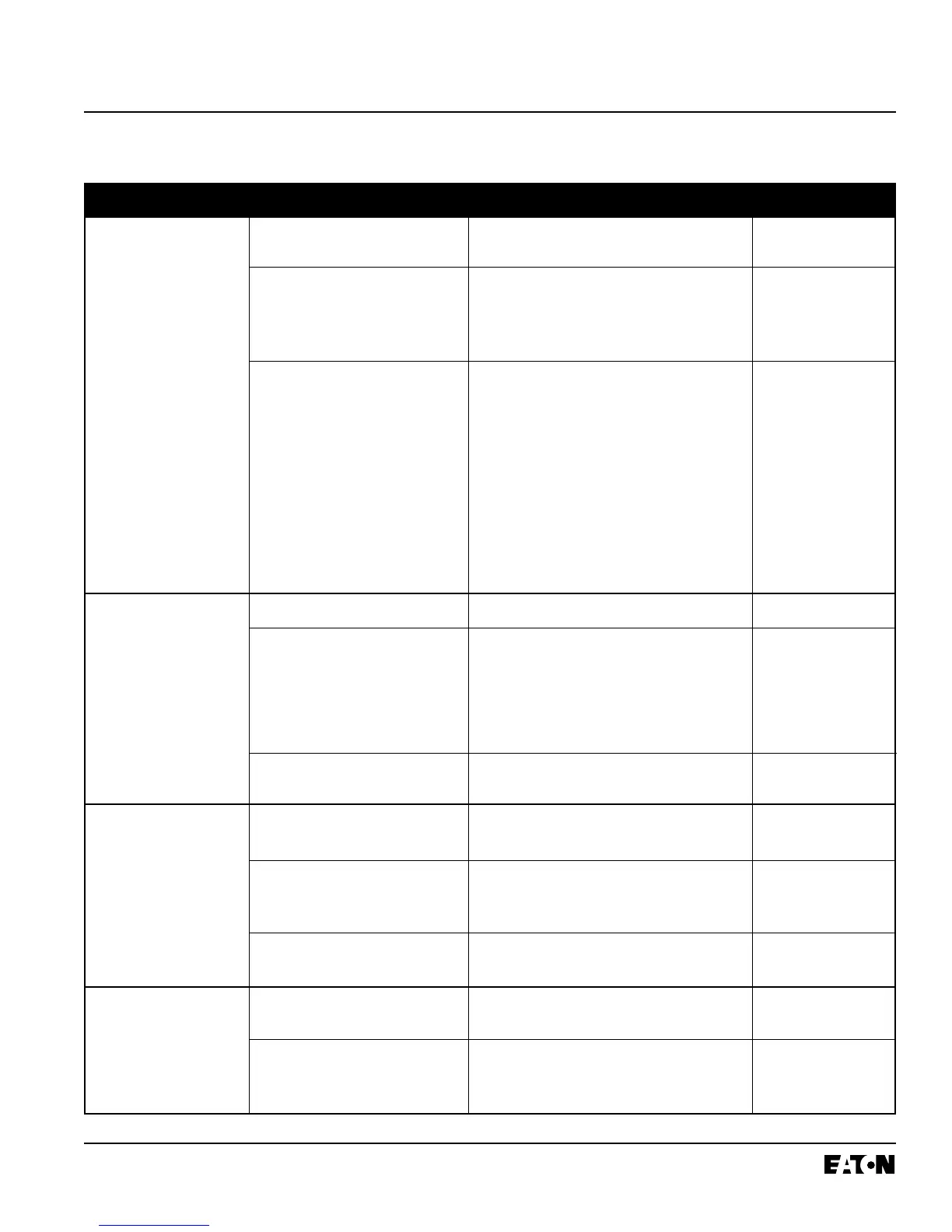
Table 5.1 Troubleshooting Guide (continued from previous page)
Symptom Probable Cause Possible Solution(s) References
 Loading...