“Connection Failure” when OPTIMizer not working or cord not Verify OPTIMizer operation on another breaker. I.B. 29C892
OPTIMizer is plugged in. properly plugged into OPTIMizer. Para. 2-2.2 & 3-2
Cord not properly plugged into Check connection. If unit status LED is blinking, Para. 2-4.1
breaker. connection is OK.
Rating plug is not installed or is Instantaneous LED will be on. Install rating plug Para. 2-6 & 5-4.2
loose. and/or check for loose connections.
Rating plug is open internally Replace rating plug Para. 5-4.2, Table 2.1
Trip unit may be the problem. Replace breaker. Refer to Note 1 at end of Para. 5-3
Table 5.1.
Ground fault alarm unit Connections to ground fault alarm Check connections Table A.1
does not operate on a unit are incorrect. Wiring Diagrams
ground fault.
Ground fault alarm is not operating Press test button on ground fault alarm unit. Table A.1
Button should illuminate. If it does not, check Instructions for
that 120V is being supplied to unit. If it is, ground fault alarm
replace the ground fault alarm unit.
Breaker is not providing an alarm Temporarily disconnect the wires to L1 and L2 Table A.1
on the ground fault alarm unit. With these con- Instructions for
nections open, approximately 5 volts should ground fault alarm
appear between GF, AL and COM when the and wiring diagrams
ground fault current exceeds pickup. On ground
fault alarm breakers, this voltage will be present
as long as pickup is exceeded. On ground fault
trip breakers, this voltage appears only trans-
iently after a trip and must be observed with an
oscilloscope. If the voltage is not present, the
problem may be in the breaker. Refer to Note 1
at the end of Table 5.1.
Breaker trips on ground There actually is a ground fault Check circuit to find the location of the fault. N.A.
fault.
On four wire systems the neutral (1) Check neutral sensor and neutral sensor Table A.1
current sensor may not have the connections on side terminal block are good. Wiring Diagrams
correct ratio or be properly con- (2) Check that the neutral current sensor ratio
nected. matches the breaker. (3) Check that connections
from the neutral current sensor to the breaker
are not reversed.
Trip unit may be the problem. Replace breaker. Refer to Note 1 at end of Para. 5-3
Table 5.1.
I.B. 29C891B
Page 47
Effective 11/98
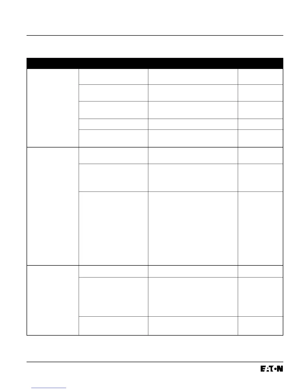
Table 5.1 Troubleshooting Guide (continued from previous page)
Symptom Probable Cause Possible Solution(s) References
 Loading...