www.cuttermasters.com - Toll Free (800) 417 2171
CUTTERMASTER Professional CM-01P User’s Manual
Page 26
Using the y axis table feed move the wheel away from the tool .150” according to your indicator. Now,
the grinding point of the wheel will follow a .150” arc around the central pivot point of the radius spin-
dle. Return the tool to the wheel, almost to touch, using the spindle upper carriage y axis feed screw.
Using the radius spindle upper carriage x axis feed screw, back the tool away from the wheel so that
it will clear the wheel when you swing the spindle through the entire radius grinding motion.
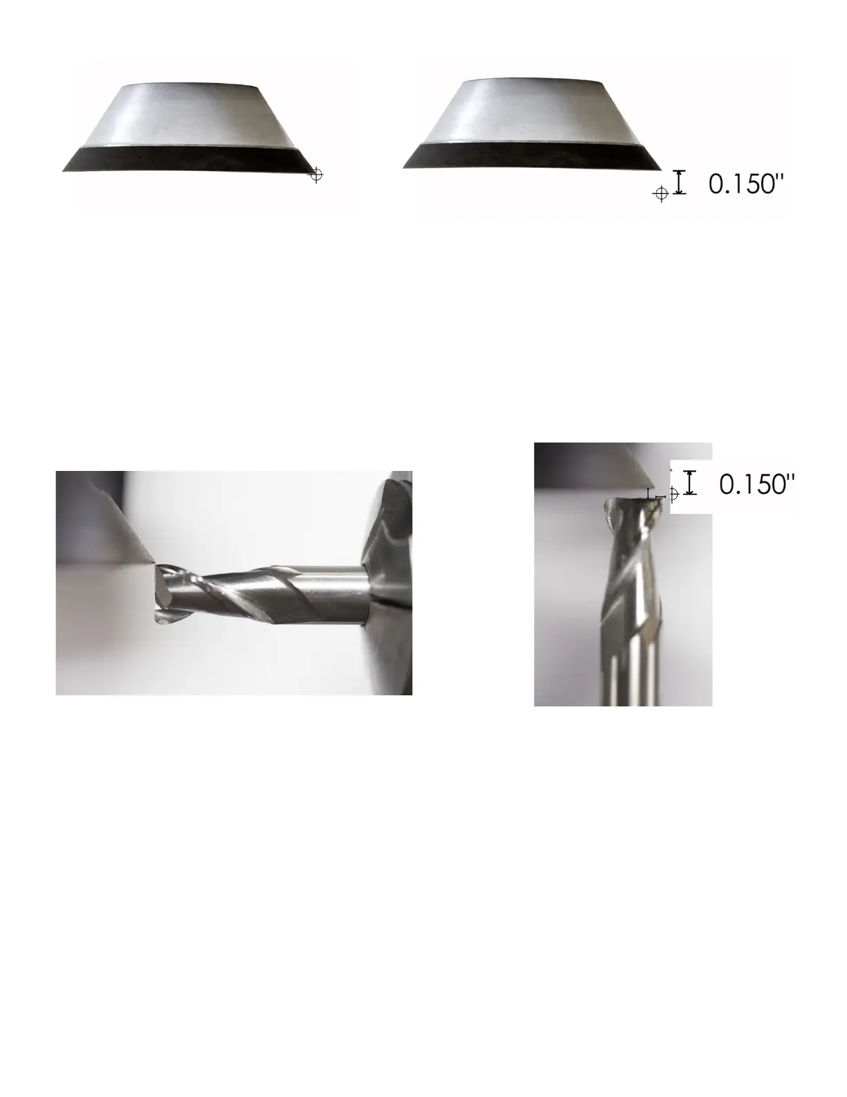
Double check: you should see that the corner of the tool is off-set from the grinding point on the
wheel by 0.150” when in line with the x axis and also when the spindle is swung so that the tool and
spindle are in line with the y axis.
Wheel is at pivot center - Indicators set to zero
Lower y axis is backed away from 0.150” for a 0.150 radius
Double check that the settings are snug: motor tower tilt and pivot.
Once you are in position, from this point you will only use the upper carriage spindle x axis feed screw
to grind.
Gibs: Tighten the radius spindle carriage red gib set screws to remove any play in the spinlde upper
carriages. Leave the outer (black) thumbscrews just snug You don’t want any movement in the air
spindlextureexceptrotation.
Keeping an eye on the corner of the tool, pivot the airspindle clockwise being careful not to nick the
wheel. If needed, move the upper x away from the wheel until it is clear.
...at full swing it should be
o set 0.150” in both axes
Double check: if the tool corner is at the wheel as
shown...
=