4
BASIC OPERATION
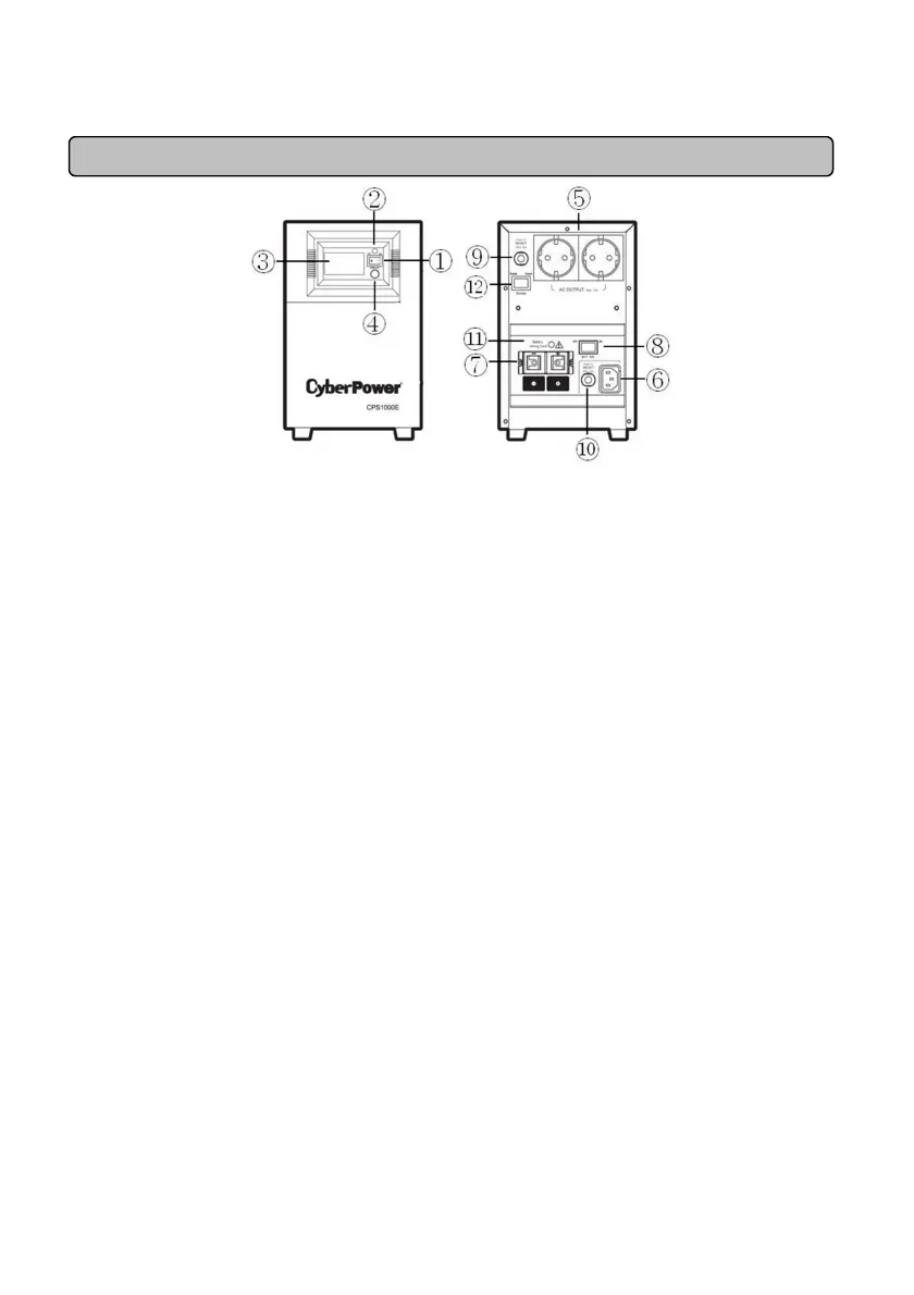
DESCRIPTION
1. Power Switch
Used as the master on/off switch for equipment connected to the AC outlets.
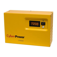
2. Power On Indicator
This LED is above the power switch. It illuminates when the utility condition is normal and the AC
outlet is providing power, free of surges and spikes.
3. Multifunction LCD Readout
High resolution and intelligent LCD display shows all the EPS information with icons and messages.
For more information please check the DEFINITIONS FOR ILLUMINATED LCD INDICATORS
section.
4. LCD Display Toggle / Selected Switch
Users can monitor EPS status and set up functions using the toggle. The buzzer on/off can also be
controlled by the toggle switch. Please refer to “EPS Status Inquiry and Functions Setup” section
for more details.
5. AC Outlet
The unit has two Schuko type outlets for connected equipment to ensure temporary uninterrupted
operation during a power failure. Max. Output is 10A; Max. Output wattage is 700W.
Note! Maximum cord length is 10 meters and the cable O.D. must be 14AWG or greater.
6. AC Inlet
AC input terminals
Note:
::
:The O.D. of the distribution cables must be 14AWG or greater.
7. DC Inlet
Battery input terminals
Note:
::
:Maximum battery wiring cable length is 2 meters and the cable O.D. must be 4AWG or
greater.
8. Battery Switch
Turn on/off the battery switch, and the battery source will be connected/disconnected to the EPS
unit. The unit will only charge in the ON position.
9. AC Output Circuit Breaker
Located on the back of the EPS, the circuit breaker serves to provide overload and fault protection.
10. AC Input Circuit Breaker
Located on the back of the EPS, the circuit breaker serves to provide overload and fault protection.
11. Battery Input Wiring Fault LED