Cybex Arc Trainer 750A/750AT Owner’s Manual
23
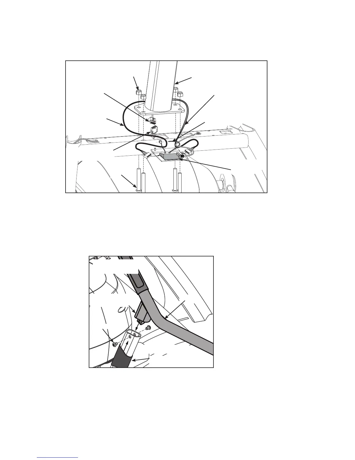
Attach750Aconsoleandhandrailassembly.
Locate four nylon locknuts (#12) and four BHSCS .375-16 x 2.25 (#13).1.
Heart Rate
Display Cable
Upper Display
Cable
Lower Display
Cable
Cable Strap
Contact Heart
Rate Cable
Heart Rate
Board
#12
#13
#2a
750A
With an assistant, place the console assembly (#2a) and handrail assembly (#2b) in the correct 2.
position on the main frame. Conrm that no cables are pinched while lowering the console.
Insert (from underneath) the four 3. BHSCS .375-16 x 2.25 (#13). Hand thread the four .375-16 nylon
locknuts (#12) in position. Do not tighten at this point.
Apply loctite4. to and insert the four BHSCS .375-16 x .50 SS (#14d). Do not tighten at this point.
#2b
(both sides)
rubber sleeve
handle-to-frame
connection
#14d
750A

 Loading...