136
Installing New Modular Cable Driver Chips - continued
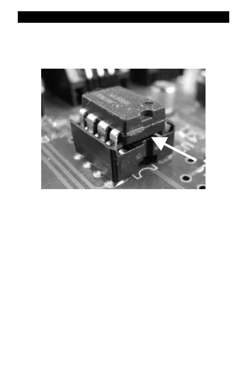
Removing Old Chips: This is easy but must be done correctly. The most common mistake made
is removing the socket instead of just the chip. The socket stays on the board. The chip is plugged
into the socket. Insert a thin flat-bladed screwdriver in the narrow gap between the socket and the
chip. Gently twist the screwdriver to lift the chip out of the socket. A closeup of the ZoneMaster
U3 is shown below illustrating the correct position of the screwdriver blade. Remove the
Command Station’s chip the same way.
Insert New Chips: Locate pin 1 on the new chip. Orient it correctly with the socket. Insert all 8
pins into the socket. Verify that all pins are in the socket and not outside, or bent up underneath
the chip. Insert the new chips in both the Command Station and the ZoneMaster.
Ready To Checkout: Plug in the modular cable between the Command Station and the
ZoneMaster booster. Turn on power to both. Verify that the ZoneMaster’s green GP light is on.
Reassemble the booster and reconnect it to the layout.
Common Problems: The most common mistake is inserting the chip without all pins going into
the socket. A pin that becomes bent up and underneath the chip is difficult to see. If in doubt,
unplug the chip, inspect and reinsert. The second most common mistake is inserting the chip
backwards into the socket. Check the pictures and then check orientation.
Safely Discard The Old Chips: Bend all the pins up under the chip to identify it as a bad part.
Discard the old chips in an appropriate trash receptacle. Do not leave them lying around where
children can find them as they are a choking hazard.
Chip
Gap
Socket
Insert blade here