22
Building The Fascia Plate Kit
1. Unpack the kit and inventory the items.
2 - headphone jacks, 2 nuts, 2 washers
2 - F-type jacks
2 - Twist on cable connectors
1 - Metal face plate
1 - Circuit board
2. Remove and discard the nut and washer from the F-type jacks.
3. Insert the F-type jack into the back side of the circuit board. The word back should be on the
same side as the threads. Solder the connector. Be sure to solder all four tabs as well as the center
pin. Solder the second F jack to the board.
4. Insert the headphone jack into the front side of the board. The jack must be oriented properly or
it will not fit the slots. Solder each jack.
5. Be sure board is oriented properly. The side marked "Toward Plate" must face the back of the
black face plate. Attach the face plate to the headphone jacks using the large washers and nuts.
Place the washer on the front of the plate and then the nut.
Do-It-Yourself Jacks
There is nothing special about the CVP fascia plate
circuit board or jacks. We designed the fascia plate
kit to simplify connections and eliminate soldering
coax cable directly to jacks. Some EasyDCC users
have asked if they could save a couple of dollars
and build their own fascia plate with hand wired
jacks. The answer is yes.
Any two conductor 1/4 inch phone jack can be used.
However, it cannot be a stereo (3 conductor jack.
Also make sure you have correctly identified the tip
(signal) and ring (ground) lugs of the jack. If you
accidentally switch the two, you will damage your
plug-in throttle. Double check your wiring on all
jacks. The tedium of soldering lots of jacks can lead
to carelessness. Jacks can be purchased at Mouser
Electronics or other similar mail-order electronic
parts suppliers.
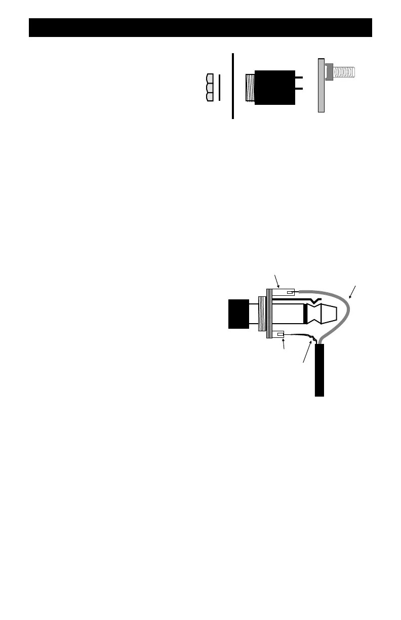
The drawing shows how to identify the plug's conductors and match to the jack’s terminals.
Some brands of jacks have the same size lug for both ground and signal. Check very carefully so
that the tip and ring are connected to the proper location on the cable. Be very careful to attach the
shield and center conductor to the proper lugs on ALL jacks. It is very easy to wire one jack
backwards during installation and not realize this has happened. The moment the throttle is
plugged into the reverse-wired jack, the throttle will be severely damaged and must be returned
to the factory for repair.
After installation, take one last look at the coax cable near the jack and verify that the shield wire,
which is the ground wire, is not shorted to the center conductor. This is easy to overlook and will
result in a short on the TBUS.
Building and Installing Fascia Plates
F-Jack
1/4” Jack
Circuit BoardFaceplate
Washer
Nut
Tip (Signal)
Ring (Ground)
Coax Shield
(Ground)
Coax Center
Conductor
Coax Cable
Throttle
Plug
1/4” Jack