21
Mounting and Hookup Of The Extender - continued
Using Twist-On F-Connectors
Extender to Command Station Link
You must use the standard 7-ft telco style modular cable the comes with the Extender. The
Extender must not be any further than 7 feet from the Command Station.
Extender Indicators and Their Meaning
There are two LED indicators on the Extender. The Green LED shows the presence of AC power.
The red LED indicates the presence of a short somewhere out in the coaxial cable. Do not attempt
to operate throttles until the short circuit is cleared. The Extender is protected against short
circuits and overloads.
Connecting The Extender's Coax Cable Socket
The Extender has a conventional "F-Jack" which connects to the coaxial cable. This jack is the
same style as found on TV cable. The black socket next to the jack is used when checking plug-in
throttles. However, once your coaxial cable throttle bus is installed, it is usually not used.
Static Electricity Protection
If your layout has carpeting, you must connect the throttle bus coaxial cable ground to a solid
earth ground. A water pipe is a good ground. The ground allows any static electricity to be
conducted to ground and not through the Command Station electronics. Use a length of wire to
connect any one of the fascia plates ground to the water pipe.
All the fascia plates should be connected in daisy-chain fashion back to the throttle extender
board using coaxial cable. For throttles buses less than 100 feet, use RG58/59 coaxial cable. This
cable is readily available and fits the twist-on connectors in the kit. Use RG6 cable for longer
runs. RG6 twist-ons are available from electronic supply stores. Minimize the length of the cable
run.
For extremely long runs, we strongly suggest the use of additional throttle extender boards.
If you don't want to use the EasyDCC fascia plates, you can substitute standard 2-conductor
headphone jacks. Their only disadvantage is the need to solder coax directly to the jack. Their use
is described later in this section.
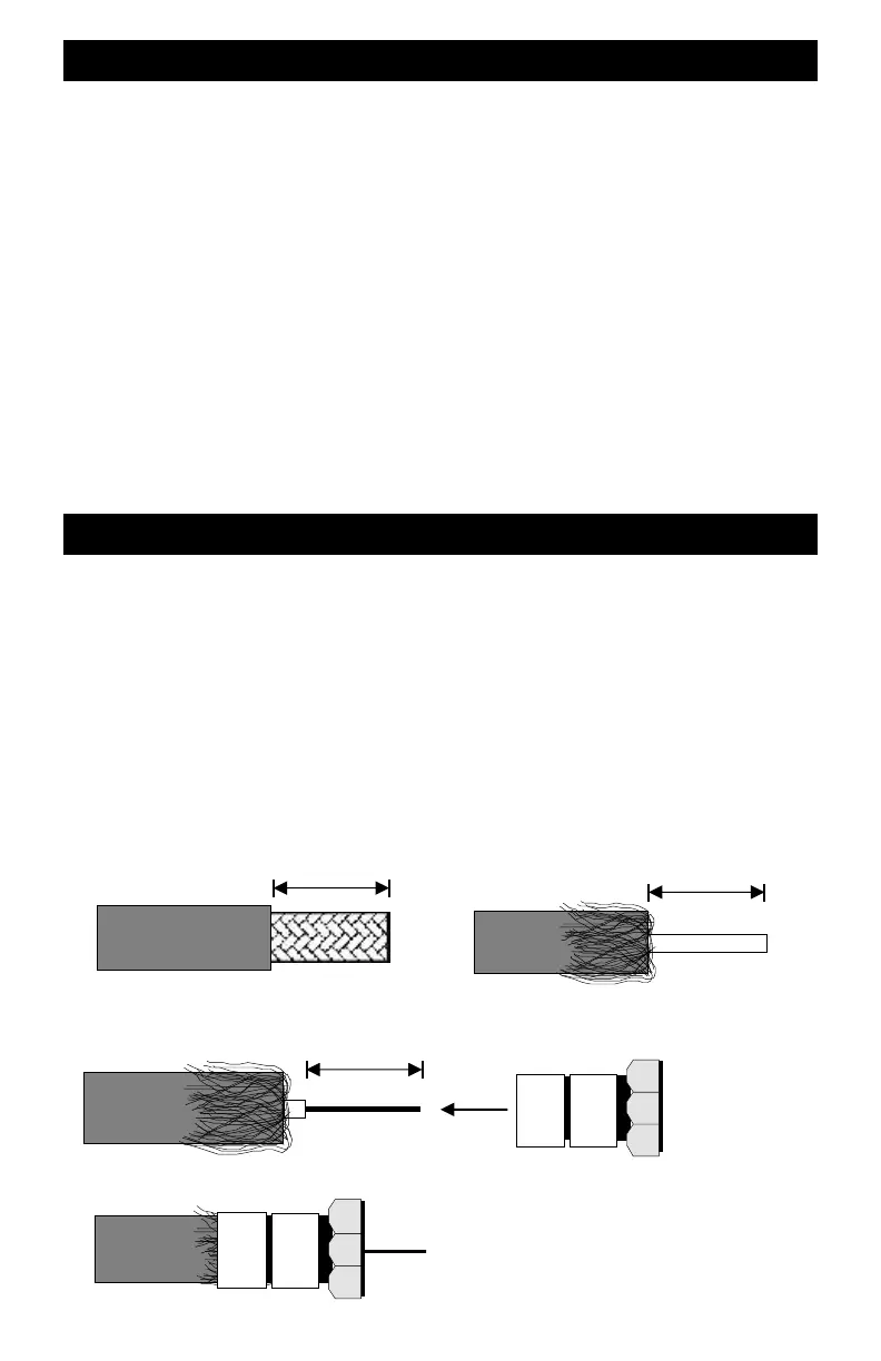
Using The Twist-On Coax Connectors
1 inch 1 inch
3/4 inch
1. Strip Outer Insulation - Do not cut braid
2. Push wire braid back over the outer insulation
3. Strip inner conductor insulation back
4. Twist connector clockwise onto shield until
tight
Twist-On
F-connector
Make sure the center conductor does not
touch the connector shell in any way.
Also make sure no small slivers of braid
are touching the center conductor.
5. Trim center conductor to extend about ¼ inch