29
Track Wiring Considerations - continued
Track Bus
Track Bus
Feeders
Feeders
Quick Check For Adequate Wiring
Go to the furthest point on the track and wiring from the booster. Use a clip lead or metal tool to
short out the track. If wiring is adequate, the ZoneMaster Booster fault indicator will light up and
the buzzer will sound. If the wiring is inadequate, the fault protection circuits will not work
properly. Improve the wiring and or add more feeders and test again.
Use Different Colors of Wire
Rail polarity is important so use different colors of wire - the brighter the better. If you have
reversing sections, consider wiring them with a third color. You might remember next week
where the wires are going, but what about in 5 years?
Using Multiple Boosters
When to add more boosters is up to you. By breaking the layout into multiple power blocks, each
with its own booster, a problem in one power block will not affect other power blocks.
Derailments and resultant shorts will not shutdown the entire railroad. We suggest creating
separate power blocks in areas where operation is concentrated. These areas include yards,
staging tracks, large towns, and large industrial areas. You can also use regions as block
boundaries. Regions can be the “west wall”, center peninsula, or levels.
Avoid creating large blocks where the entire block is not visible during normal operation. A good
example of this is single block serving a peninsula with a tall center divider. A derailment on one
side shuts down the opposite side. This leaves the operator scratching his head looking for the
problem on his side of the divider when in fact it is on the opposite side.
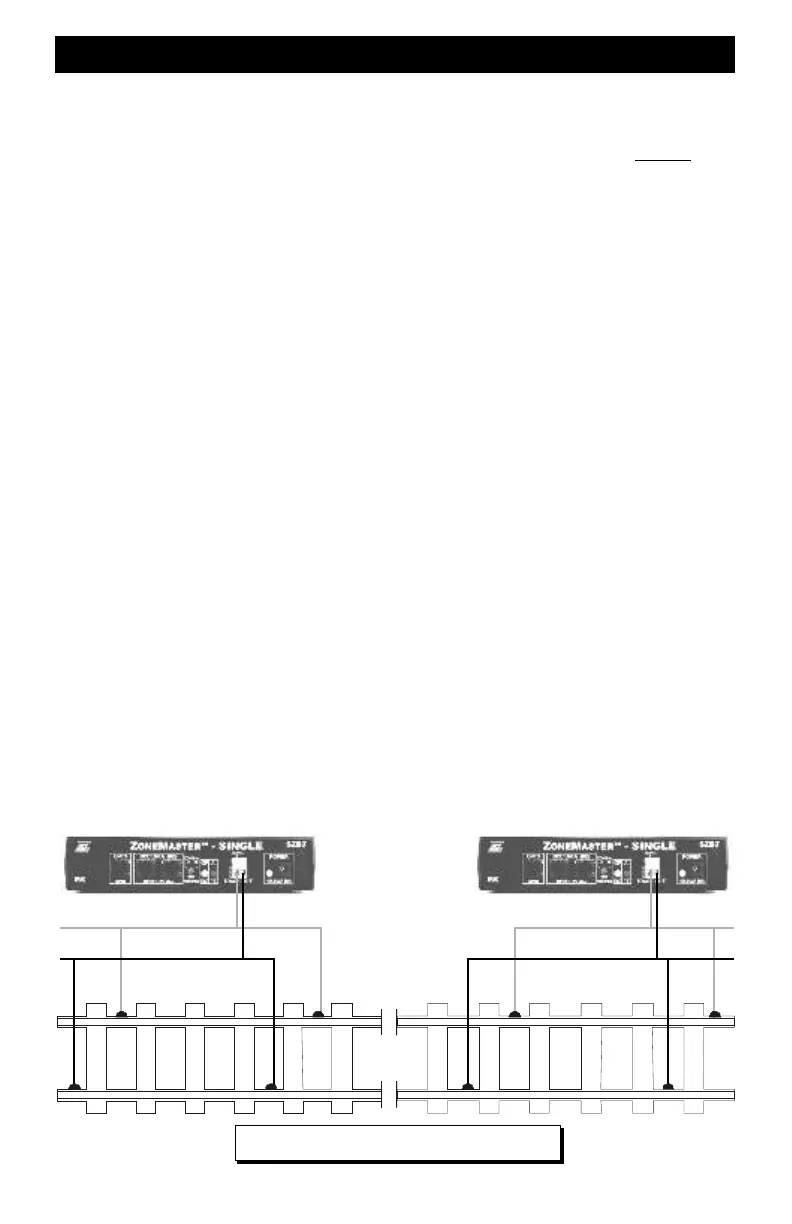
Creating Power Zones or Blocks
Gap both rails at each end of the power block.. Don't forget to also cut gaps in the large power
buses feeding the block. Do not parallel booster outputs – this is not allowed and may damage the
booster.
Booster Outputs Must Be Connected Properly
Be sure to properly “phase” booster outputs. This will allow locomotives to cross gaps without
shorting out the boosters. Adopt the methodology of having the left terminal connect to a specific
rail or bus wire (outside, left, etc) and the right terminal connected to the other rail or bus wire.
Connecting Command Station to Boosters - Small Layouts
Connect the Command Station’s “BOOSTERS” jack to the first booster using modular telco
cable. Connect another modular cable from the first booster to the next booster. Try to limit the
total cable length to about 100 feet and no more than 5 ZoneMaster boosters. If you need more
length or have more boosters, you will need to use the CVP DISTYAMP.
continued on next page
Power Zone or BlockPower Zone or Block
Rail
Gaps
Common Rail Wiring Is Not Allowed