31
Using Multiple ZoneMaster Boosters
Unless you are operating the trains by yourself, you will want to have multiple boosters to both
spread the power load and to isolate operators from each other. As mentioned at the beginning of
this section, multiple zones are actually for the convenience of your operators. A derailment by
one operator in his town or yard, should not affect another operator in an adjacent town or out on
the mainline.
Power Zone Considerations
By breaking the layout into multiple power blocks, each with its own ZoneMaster booster, a
problem in one power block will not affect other power blocks. Derailments and resultant shorts
will not shutdown the entire railroad. Where to add more boosters is up to you although there are
a few common sense considerations.
We suggest creating separate power blocks in areas where operation is concentrated. These areas
include yards, staging tracks, large towns, and large industrial areas. You can also use physical
regions as block boundaries. A physical region can be the “west wall”, center peninsula, or even
top or bottom levels.
Avoid creating large power blocks where the entire block is not entirely visible to an operator. A
good example of this is single block serving a peninsula with a tall center scenic divider. A
derailment on one side of the divider shuts down the opposite side. This leaves an operator
scratching his head and looking for the cause on his side when in fact it is on the opposite side and
caused by the other operator.
Do Not Share A DCPS120 Power Supply
Although technically this is OK, in reality, it doesn’t work. The high surge current demands of
sound-equipped locomotives requires the entire capacity of the power supply. If the power
supply is already partially loaded by a second ZoneMaster, a sudden demand for surge current by
the first ZoneMaster will likely cause an overload and the power supply will shut down. Always
use one power supply per ZoneMaster.
Booster Outputs Must Be Connected Properly
Be sure to properly “phase” the ZoneMaster booster outputs. This will allow locomotives to
cross gaps without shorting out the boosters. Adopt the methodology of having the left terminal
connect to a specific rail or bus wire (outside, left, etc) and the right terminal connected to the
other rail or bus wire.
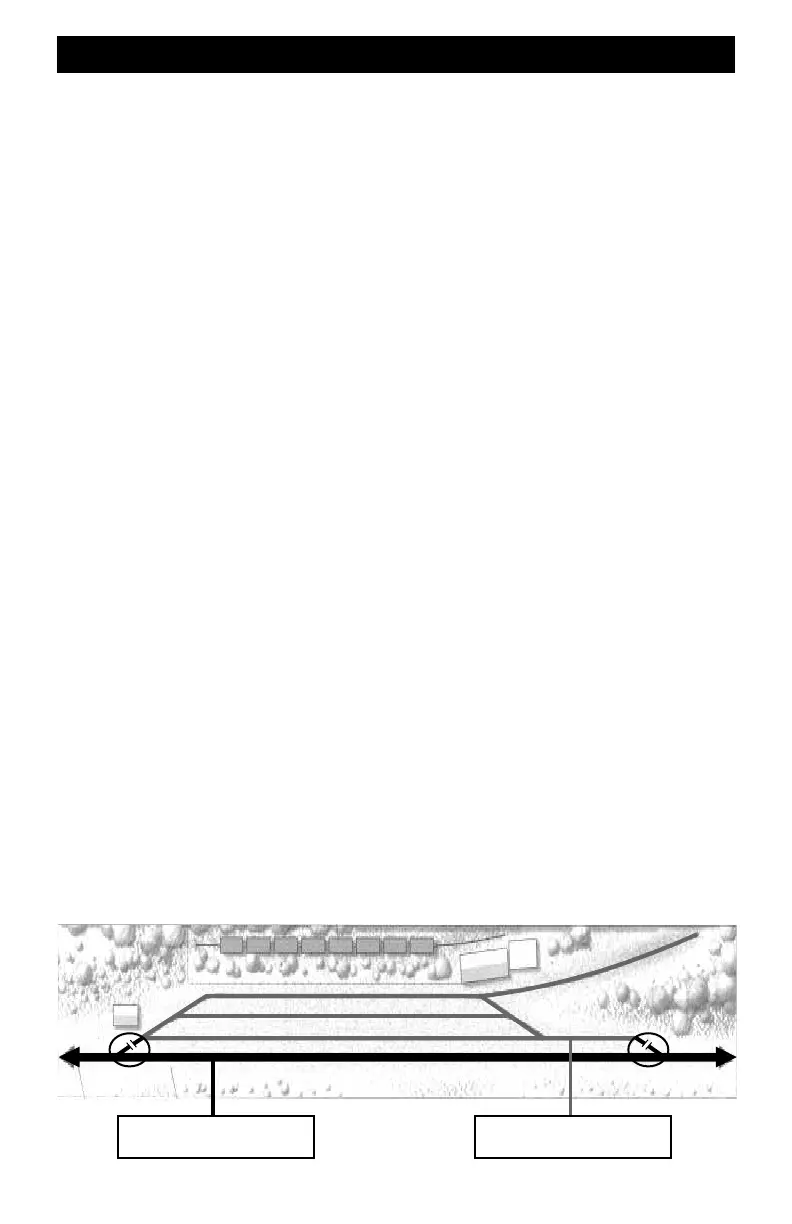
A Power Zone Example
The drawing below shows a double-ended siding off the main line that serves a small town. The
circled areas show the locations of the isolating gaps. This type of diagram is called a straignt-
line track diagram and one line represents both rails. So, make sure both rails are gapped.The
mainline is connected to a ZoneMaster and the town is connected to a separate ZoneMaster. With
this type of isolation, a derailment by the local town operator will not affect the mainline operator
or vis versa.
The ZoneMaster Single Output is shown although a ZoneMaster Dual Output can be used if there
is only one or two locomotives operating inside the town.
ZoneMaster Booster ZoneMaster Booster
Mainline
Town