8
Extended Starter System - Quick Start continued
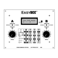
DCPS120 Booster Power Supply
The DCPS120 power supply has a universal AC
input. It can use an AC line voltage that ranges from
a low of about 100V up to a maximum of about 240
volts.
Before using the power supply, set the voltage selector switch to the far left, at the 15V setting.
This is the best setting for N, HO, S and O scale locomotives. This setting allows the decoder to
drive the motor with about the same voltage as a standard power pack.
Caution: Only use the CVP DCPS120 power supply for the ZoneMasters. Using any other type
of power supply will void the warranty and likely damage the booster.
ZoneMaster Booster
The power supply’s output cable is thick and heavy and exerts a lot of force on the ZoneMaster
input power jack. Be careful not to allow the cable to dangle unsupported from the ZoneMaster
input power jack.
The Track Output terminal is actually a plug and it can be easily pulled out to make hookup
easier. Connect the test track to the output terminal using solid or stranded wire. Small diameter
wire is OK for the temporary test track.
Command Station Programming Track
The final two connections hookup up the programming track to the Command Station. This is not
necessary for the temporary checkout unless you want to play with decoder programming. Small
diameter wire is OK since only one locomotive at a time can use the programming track.
Extender Power Transformer
Connect the 2nd and larger 12VAC/1.5A transformer to the power input jacks of the Extender
circuit board. Use 20AWG wire for the connections. Since the transformer and the Extender use
screw terminal strips, strip the wire back about 1 inch and tin the wire to keep the strands together.
Form the wire into a loop and slip it under the terminal and tighten the screw. Also, there is no
case for the Extender since it is designed for under layout mounting. Therefore, the bottom of the
circuit board must not touch any conductive surface such as a metal table.
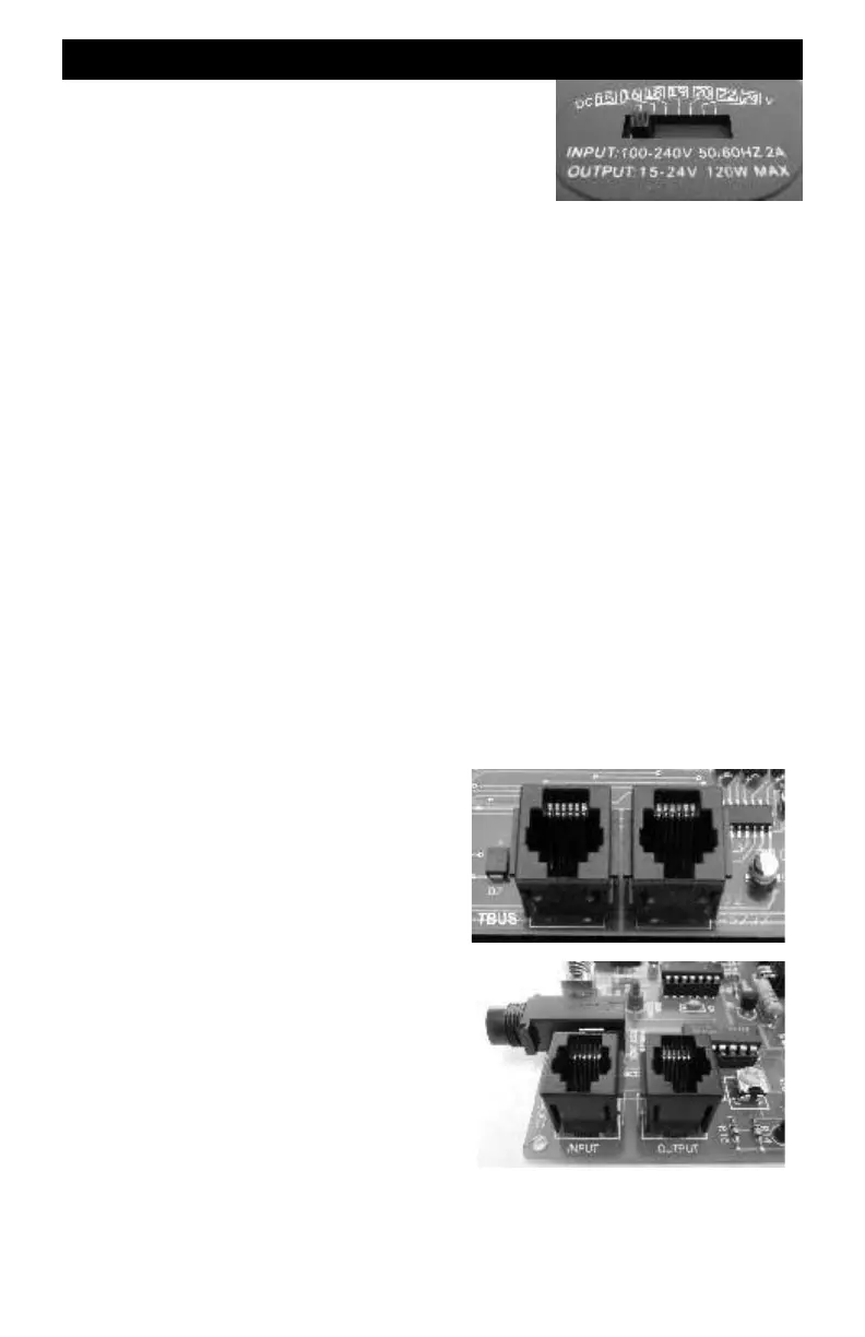
Extender To Command Station Modular Cable
You must use the gray modular cable supplied with
the extender to connect it to the Command Station.
Plug one end of the cable into the socket labeled
TBUS and the other end into the Extender’s modular
jack labeled INPUT.
Do not accidentally plug the cable into the wrong
Command Station socket.
Do not plug the cable into the Extender’s jack
labeled OUTPUT. No harm is done but the plug-in
throttle will not work properly.
When plugging the cable into the socket, do not
force it. The plug will insert easily and lock with an
audible click. To release the plug, push down on the
little plastic tab and gently pull the cable out of the
socket.
Throttle Hookup
Plug the throttle into the test jack on the Extender. The fascia plate is not needed for this
temporary checkout. Fascia plate installation is covered in a later section.
Command Station
Extender