D-Link Unified Access System Software User Manual
02/15/2011
Page 48 Document 34CS3000-SWUM104-D10
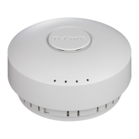
Figure 26: DWS-3026 with optional DEM-410X module installed
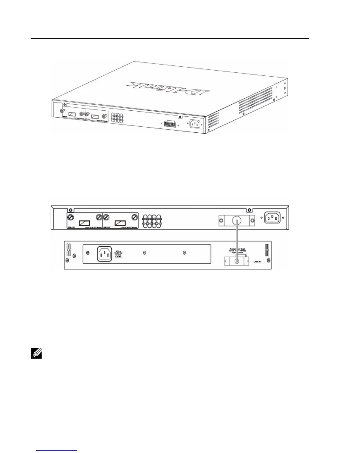
Connecting to the External Redundant Power System
The Switch supports an external redundant power system (RPS). The diagrams below illustrate a proper RPS power
connection to the Switch. Please consult the documentation for information on power cabling and connectors and setup
procedure.
Figure 27: RPS Connector
CONNECTING THE SWITCH
This section describes how to connect the following nodes:
• Switch to the network
• AP directly to the Switch
• AP to the Switch through the L2/L3 network
• Switch through the 10GB uplink to the network core
Note: All 24 high-performance N-Way Ethernet ports can support both MDI-II and MDI-X connections.
DWS-3026
DPS-600
RPS Connector
 Loading...