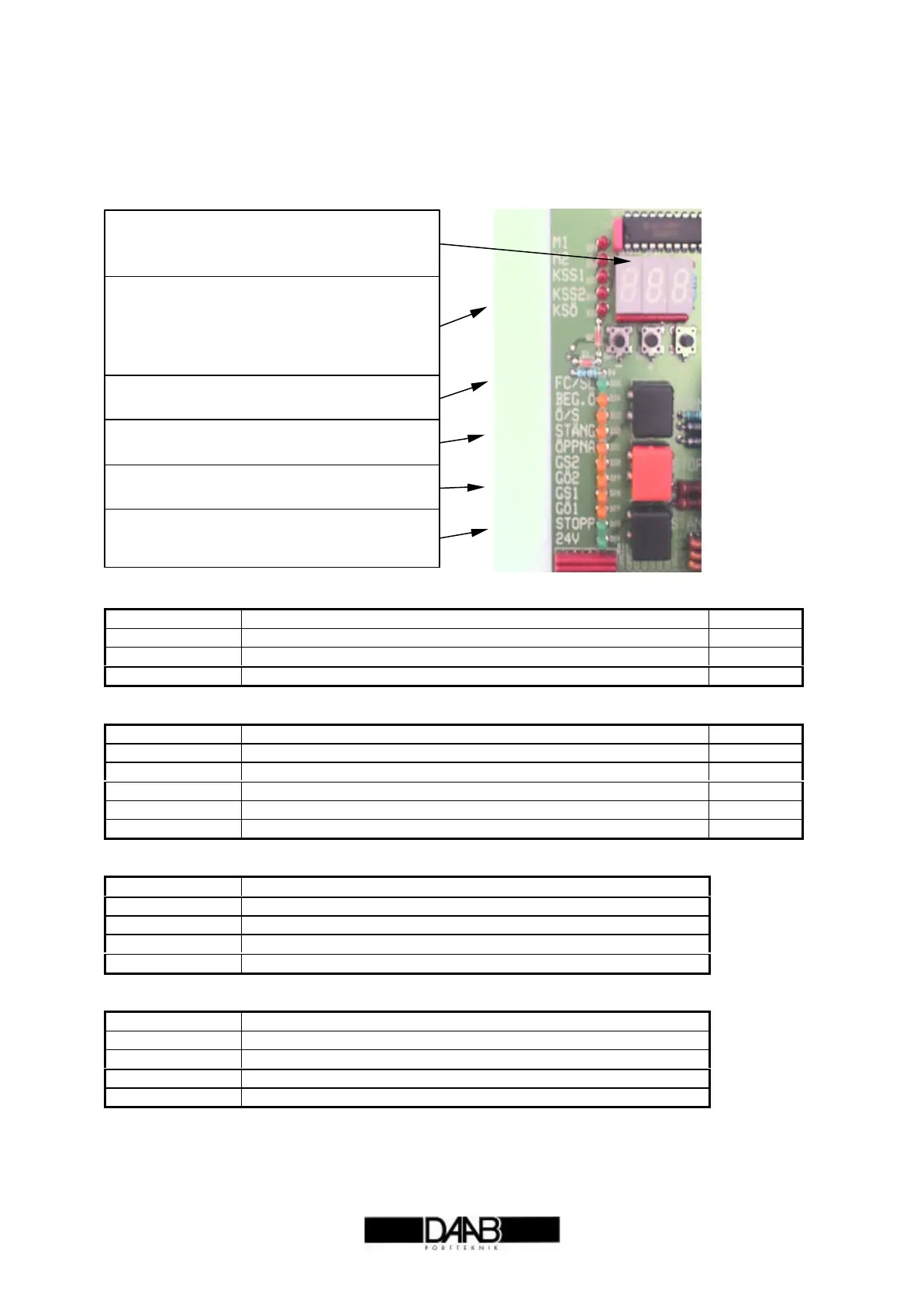
Display Diodes
To make matters easier when commissioning and fault-finding, light diodes are provided to indicate
faults and input signals.
Green light diodes normally on
Indication Function Normally
FC/SL Indicates that photocell/loop circuit is live and unbroken. On
24V DC Indicates the presence of voltage. On
STOPP Indicates that stop circuit is live and unbroken. On
Red light diodes for alarm
Indication Function Normally
M1 Indicates that the load sensor has tripped out for motor 1. Off
M2 Indicates that the load sensor has tripped out for motor 2. Off
KSS1 Indicates an error on safety buffer circuit ‘closing 1’. Off
KSS2 Indicates an error on safety buffer circuit ‘closing 2’. Off
KSÖ Indicates an error on safety buffer circuit ‘opening’ Off
Yellow light diodes indicating signals from limit positions
Indication Function
GÖ1 Lit indicates that motor 1 can open more, off in open position
GS1 Lit indicates that motor 1 can close more, off in closed position
GÖ2 Lit indicates that motor 2 can open more, off in open position
GS2 Lit indicates that motor 2 can close more, off in closed position
Yellow light diodes indicating control signals
Indication Function
O/S Indicates signal for open/stop/close remote button. Prog input 1
BEG.O Indicates signal for partial opening. Prog input 2
STÄNG Indicates signal for close.
ÖPPNA Indicates signal for open.
Red light diodes for error indication
Unlit diode means no error.
Lit diode means error.
Flashing light diode means previous error,
diode goes off next time gate is operated.
Green photocell diode normally on
Unlit means photocell/loop is actuated.
Yellow light diodes for control keys
Lit diode means key actuated.
Yellow light diodes for limit position
Lit diode goes off when limit reached.
Green light diodes normally on
’Stopp’ diode goes out when stop is actuated
and stop circuit is broken.