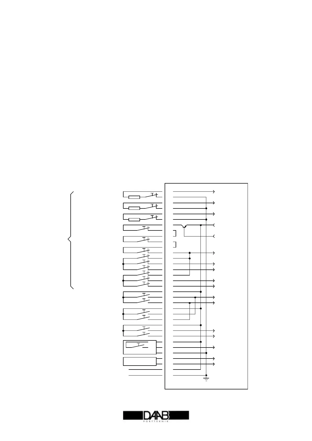
Low voltage connection
Remember!
• Connection should only be carried out by a competent person. It is important that any personal
electrostatic charge is discharged prior to working on the panel.
• The panel must be isolated from the power supply prior to commencing work.
• Remember that the gate may become dangerous if incorrectly connected.
• Do not connect anything in the safety circuit, e.g. relays or lamps, that may interfere with the
Safety circuit. If an intermediate relay must be used to obtain open and closed signals, DAAB
Should be contacted for instructions.
Safety buffers, stop and limit switches are considered part of the safety circuit.
• Safety buffer circuits must contain a 2.0KΩ resistor to ensure that if the circuit fails, it fails ’safe’.
• This control panel is designed for many applications therefore not all the input signals may be
needed.
• Un-used “Stop” terminals to be linked, and photocell / loop terminals to be linked if not used.
For explanation of the input signals see the next page.
To remain ’fail safe’ Photocell/loop detectors, when powered must have normally closed contacts, and
when actuated or failed they must revert to open circuit.
1
2
3
4
5
6
7
8
9
10
11
12
13
14
15
16
17
18
19
20
21
22
23
24
25
26
27
28
29
30
31
32
33
34
+
-
-
+
UT
KSS1
KSS2
KSÖ
TB1
GÖ1
GS1
TB2
GÖ2
GS2
RS 485
24VDC
Stop
Stop
Stop
Close
Open
Open
Close
Communication
Open/stop/close
Photocell/loop
Part opening
Safety
Output for 24VDC
max 300mA
Control panel
Safetycircuit