Do you have a question about the DAAB EP102 and is the answer not in the manual?
Describes the purpose of the EP102 control panel for various gate types.
Explains EP102 as DAAB's standard automatic control panel system.
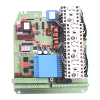
Lists and describes the components of the automatic control panel.
Dimensions, weight, supply voltage, fuses, power, temperature.
Motor types, safety buffers, safety/stop circuits, limit position, motor protection, load sensor.
Digital inputs, photocell supply, and communication protocol.
Explains the importance of correct assembly and connection for safety.
Lists important safety and compatibility checks for power supply.
Diagrams for 3x400V, 3x230V, and single-phase 230V power supplies.
Shows diagrams for Y, D, and single-phase motor connections.
Safety precautions for low voltage connections, isolation, and circuit integrity.
Requirement for photocell/loop detectors to be normally closed.
Safety buffers, stop circuits, limit positions, and control keys.
Photocell/loop inputs, communication, and 24V DC output.
Explains resistor placement in safety circuits for fail-safe operation.
Diagrams for mechanical and solid-state safety buffer connections.
Guidelines for cable selection and polarity for panel communication.
Important checks before powering up the system.
Essential adjustments for limit position, direction, load sensor, controls, and running time.
Verifying system status on power-up and checking display indicators.
Explains red, green, and yellow diodes for errors, status, and controls.
Details red diodes for alarms and yellow diodes for limit/control signals.
How values are stored in channels and displayed on the unit.
Information on save mode, locked settings, and error message display.
Step-by-step guides for reading and writing parameter values.
Guidance on handling errors and recording configuration settings.
Lists components of the safety circuit and their roles.
How safety buffers are monitored and how to set their number and function.
Setting the delay for magnetic lock release before gate opening.
Setting delay for gate leaf overlap or magnetic lock.
How to check and correct motor rotation direction.
Procedure to adjust limit positions and identify potential issues.
How the load sensor works, its settings, and how to check phase sequence.
How to read motor load values from the display.
Guide to setting load limits for motors and testing for judder.
Explains motor protection tripping and error messages.
How to measure and set the limited running time for equipment protection.
Explains deadman vs. latched control and C33 setting.
Verifying load sensor, safety buffer, and photocell operation.
How the system reverts to deadman control and how to disable it (C46).
Setting priority for open/close commands (C63 options).
Setting a preset time for the gate to close automatically.
How the stop key affects automatic closure and its settings (C52, C53).
How automatic closure is timed based on loop detection and its settings (C51, C54).
Setting time and leaf selection for partial opening.
Covers Open/Stop/Close, Interlock, Auto-closing, and other functions.
EP102 panels can communicate and send interlocks.
Notes on commissioning and program version for interlock functions.
Allows only one door to open at a time to prevent heat loss.
Interlocking doors to open only one at a time for draught exclusion.
Achieving high security and speed with combined gate and barrier.
Setting C95 for communication between EP102 panels.
Setting C64 for heat lock, blocking open, and blocking close.
Explains blocking functions and combinations for two doors.
Table detailing blocking function combinations and their explanations.
Lists channels for reading measured values and their ranges.
Lists channels for setting parameters during commissioning.
Channels for setting delay times for gate halves and magnetic locks.
Channels for safety buffers, load sensor, and motor protection settings.
Channels for automatic closure and photocell/loop closure.
Channels for partial opening, programmable inputs, and door blocking.
Setting channel C70 for supplementary card display.
Channels for time delays (C90-C94) and communication (C95, C99).
Checking voltage presence and error messages.
Verifying stop circuit, alarms, limit switches, and input signals.
Checking internal buttons and overall system response.
Errors E01-E03 related to motor protection and running time.
Errors E04-E08 related to safety, illegal running, and voltage dips.
Errors E09-E15 related to program watchdog, clock, memory, communication, and voltage dips.
Defines acronyms used in the manual like BEG.Ö, FC, KSS, KSÖ, etc.
Lists available accessories and their functions.
Information on finding the valid program version and object number.
| Brand | DAAB |
|---|---|
| Model | EP102 |
| Category | Control Panel |
| Language | English |