ENGLISH
40
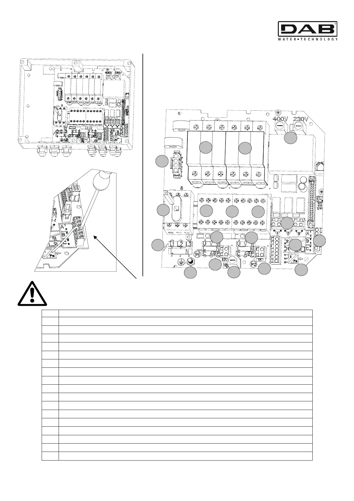
8. CONNECTION DIAGRAM REFERENCE
To allow the wire to be inserted in the spring terminals, press the button with
a screwdriver. Ensure that the wire is completely inserted, after having released
the button!
Ref.
Function
1 QS1 – power supply line insulating switch
2 Power supply line connections
3 Earthing connection
4 Pump P1 and P2 control contactors
5
Pump P1 connection
6
Pump P2 connection
7 K-K – Thermal protection input for the motor
8 FU3 – fuse protecting the transformer against incorrect connection of motor cables
9 A-B-C – Terminals connecting digital inputs for level or pressure control
10 R-N – Terminals connecting digital alarm inputs
11
H1 – Terminal connecting pressure sensor analog input
12
Q1-Q2-Q3 – Terminals connecting the alarms
13 FU1-FU2 – Fuses protecting the transformer against short circuits
14 FU5 – Fuse protecting pump P2
15 FU4 – Fuse protecting pump P1
16 Connector for power supply to EXP board (optional)
17
13-14 – Connecting terminals for indicating pumps being fed (P1 and P2)
1
2
3
4
5
6
7
8
9
10
11
12
13
14
15
16
17
17
7