ENGLISH
GB
77
)RUWKHLQVWDOOHULWZLOOEHVXI¿FLHQWWRZLUHXSWKHGHVLUHGLQSXWDQGRXWSXW
FRQWDFWVDQGWRFRQ¿JXUHWKHLUIXQFWLRQVDVGHVLUHGVHHSDUDJUDSKV
7.7.8 - Setup of the auxiliary digital inputs IN1, IN2, IN3, IN4 and 7.8 -
Setup of the outputs OUT1, OUT2).
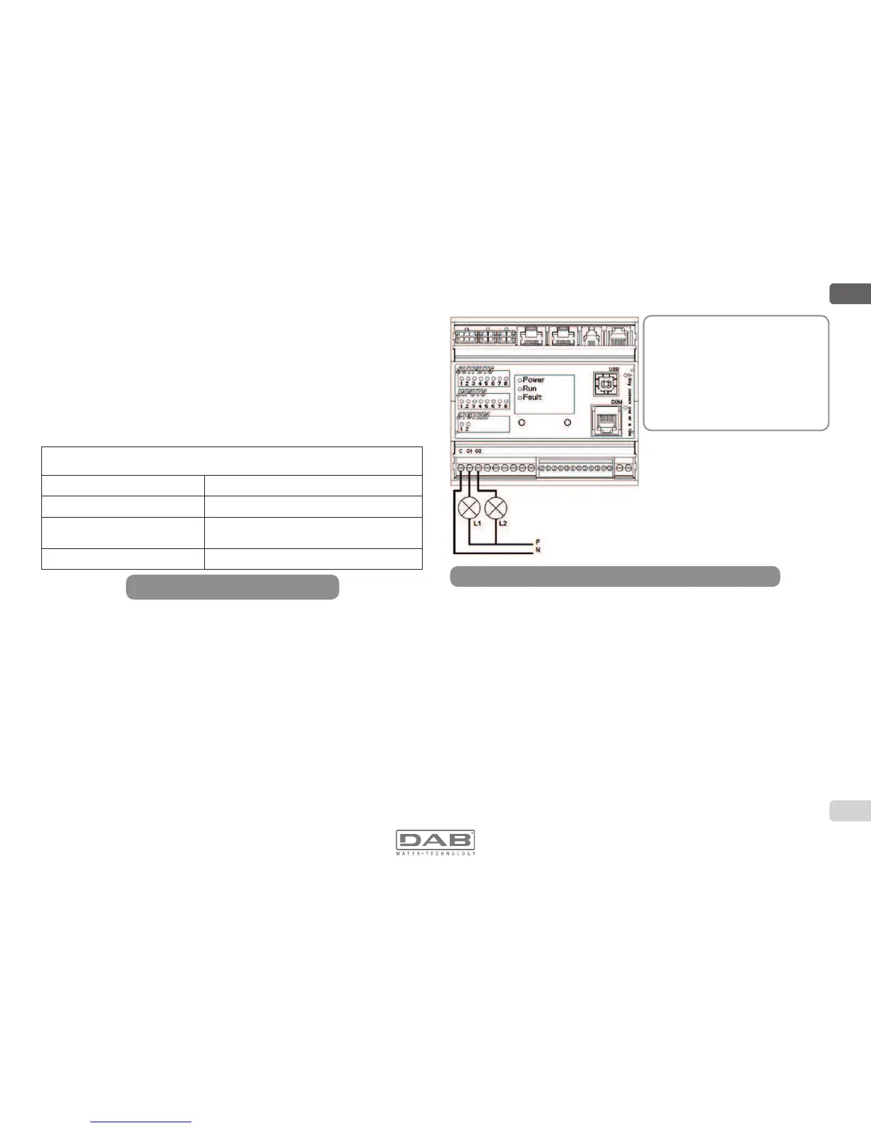
Output contacts OUT 1 and OUT 2:
The connections of the outputs listed below refer to the 9-pole terminal
board on the input output control unit, indicated with screen printing O1,
O2 and C.
Characteristics of the output contacts
Type of contact NO
Max. bearable voltage [V] 250
Max. bearable current [A]
5 -> resistive load
2,5 -> resistive load
Max. accepted cable section [mm²] 2,5
Table 4: Characteristics of the output contacts
Input connections (photocoupled)
The connections of the outputs listed below refer to the 12-pole terminal
board on the I/O control unit, indicated with screen printing I1, I2, C,
GND, VS.
- I1: Pin 2 and 3
- I2: Pin 3 and 4
- I3: Pin 5 and 6
- I4: Pin 6 and 7
The inputs may be powered with either direct or alternating current at a
50-60 Hz. Shown below are the electrical characteristics of the inputs,
Table 2.
Figure 13: Example of connection of the outputs to the I/O control unit
With reference to the example
proposed in Figure 1:
/VLDFFHQGHTXDQGRODSRPSD
è in blocco (es. “BL”: blocco man
canza acqua).
/LVOLWZKHQWKHSXPSLV
running ( “GO”).
 Loading...