The Dado Lab QB1 is a constant flow sampler designed for various environmental and industrial sampling applications, including workplace atmospheres, stack emissions, and general environmental monitoring. It is compliant with several international standards such as UNI EN ISO 13137:2015 for chemical agent sampling, UNI EN 13284-1:2017 for low-range dust concentration, UNI EN 1911 for gaseous chlorides, UNI EN 14385 for total emission of various metals, UNI EN 13211 for total mercury, CEN/TS 13649:2014 for individual gaseous organic compounds, and UNI EN ISO 16000-7 for airborne asbestos fibre concentrations. The device is also CE marked and complies with Low Voltage Instruments Directive BT 2014/35/UE, RoHS Directive 2011/65/UE, EMC Directive 2014/30/UE, and Machinery Directive 2006/42/EC.
The QB1 is supplied with a power cable, a sampling line quick connector, a hose barb for leak checks, and an operation quick guide. Upon receiving the goods, it is crucial to verify the order's correspondence and the content's integrity. Any damage to the package must be noted on the delivery paper before signing, or the delivery can be refused with written notification. Damages found after unpacking must be reported within 8 days (D.D.T) to the courier. All units undergo factory testing and calibration, with a report detailing results and acceptability verification.
Safety Rules and Precautions
For safe operation, users must adhere to specific safety rules. The enclosure panels should never be removed without first turning off the instrument and disconnecting the power supply. The QB1 must always be connected to a grounded power socket. Outdoor operation requires protection from weather elements like rain and humidity. Before use, the sampler should be placed on a flat, stable surface with adequate surrounding space for ventilation. The operating temperature range is -10°C to 40°C, and the maximum sampled gas temperature is 45°C. Contact with and sampling of corrosive and flammable compounds should be avoided.
To prevent damage and extend the lifetime of components like the pump and dry gas meter, it is essential to ensure that gases entering the QB1 are dry. If very wet or condensing gases are sampled, the device should be allowed to work with open air for at least 10 minutes after the operation.
Technical Specifications
The QB1 series offers several models (V1.5, V3.0, V5.0, V1.5DC, V2x5DC, QB1-D), each with specific characteristics.
Common specifications include:
- Sampled gas conditions: Dry, with a maximum temperature of 45°C.
- Gas inlet: Equipped with a protection filter and quick connector.
- Working temperature: -10°C to 40°C at 95% UR.
- Storage temperature: -10°C to 50°C at 95% UR.
- Construction: Inox steel and aluminum.
- Size: 330 x 310 x 360 mm (L x P x H).
Volume Measurement:
- Dry gas meter: Class G1.6.
- Flowrate range: 0.016 m³/h to 2.5 m³/h.
- Accuracy: 2% of the measure.
- Resolution: 0.1 liters.
Ball Flow Meter:
- Range: Varies by model (see table).
- Accuracy: 5% f.s.
Dry Gas Meter Temperature:
- Range: -50°C to 70°C.
- Accuracy: ± 1°C.
- Resolution: 0.1°C.
Suction Pressure Drop (excluding V2x5DC model):
- Vacuum meter range: 0 to 1 Bar.
- Accuracy: ± 5%.
Model-Specific Characteristics:
- QB1 V1.5: Single head diaphragm pump, 32 l/min nominal max flowrate, 0.2-3.0 Nl/min flowmeters scale, 9.5 Kg, 230Vac ± 10% 50/60Hz - 50 W power, Fuse 1.6A.
- QB1 V3.0: Double head diaphragm pump, 55 l/min nominal max flowrate, 0.2-3.0 Nl/min flowmeters scale, 11 Kg, 230Vac ± 10% 50/60Hz - 100 W power, Fuse 1.6A.
- QB1 V5.0: Rotary vane pump, 75 l/min nominal max flowrate, 2-30 Nl/min flowmeters scale, 13 Kg, 230Vac ± 10% 50/60Hz - 150 W power, Fuse 3.15A.
- QB1 V1.5DC: Single head diaphragm 24Vdc pump, 16 l/min nominal max flowrate, 0.2-3.0 Nl/min flowmeters scale, 9 Kg without battery, 230Vac ± 10% 50/60Hz - 50 W power (Fuse 1.6A), with external connector, power consumption 2.5 Ah.
- QB1 V2x5DC: x2 Single head diaphragm 24Vdc pumps, 11 l/min nominal max flowrate, 0.2-5.0 Nl/min flowmeters scale, 13 Kg including batteries, 230Vac ± 10% 50/60Hz power (Fuse 1.6A), x2 12Vdc 2.3 Ah built-in batteries.
- QB1-D: x2 Single head diaphragm 24Vdc pumps, 5 l/min nominal max flowrate, 0.1-2.0 Nl/min flowmeters scale, 13 Kg including batteries, 230Vac ± 10% 50/60Hz power (Fuse 1.6A), x2 12Vdc 2.3 Ah built-in batteries. This special version is dedicated to VOCs sampling according to EN13649, requiring dilution of the sample with cleaned and dehydrated ambient air.
Usage Features
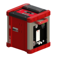
Connections Panel:
The QB1 features a connections panel that varies slightly across models. Common elements include:
- Vacuum meter (0-1 Bar) indicating line pressure drop.
- Ball flowmeter (Nl/min @ 20°C, 101.3 kPa) with an indication scale.
- Water trap inspection window.
- Dust protection filter cap.
- Sampling line quick connector.
- Flow regulation knobs (ranges vary by model).
- Sampled gas exhaust (1/8" gas threaded connector).
- Protection fuse box.
- Power switch.
- Some DC models include an external battery connector.
- The QB1 V5.0 has a bypass valve for leak checks.
- The QB1 V2x5DC has two independent sampling lines, each with its own vacuum meter, flow regulation knob, ball flowmeter, and sampled gas exhaust.
Controls Panel:
The controls panel also varies by model but generally includes:
- Polycarbonate protection cover.
- Turn-on timer programmer.
- Temperature display for sampled gas.
- Dry Gas Meter with 0.1 liters resolution.
- Battery power switch (DC models).
- Reset button after battery recharge (DC models).
- Battery status LED (Green for charged, Yellow for low, Red for very low) (DC models).
Timer Setup:
The timer allows programming up to six turn-on and turn-off cycles within the same day.
- Date and Time: Press 'C' to reset the program, then hold 'P' and press 'D+' for day, 'H+' for hour, 'M+' for minutes. The instrument has a Lithium battery for backup and automatic restart after power failure, which recharges when connected to power and switched on.
- Pump Manual ON/OFF: The 'MANUAL' key forces the pump to start and is active even during a timed program. Each press cycles through 'AUTO' (automatic program execution), 'OFF' (pump off), and 'ON' (pump on).
- Programming Timed Sampling: Press 'P' to display "MO ON --:--". Use 'D+' to select the day (15 combinations), 'H+' for the hour, and 'M+' for the minutes of the first turn-on. Repeat for turn-off ("MO OFF --:--"). Press 'P' to confirm. To add more cycles, proceed with the second ON. Press 'P' to activate the program.
Thermometer:
The thermometer displays the sampled gas temperature inside the dry gas meter in °C. This value is used to normalize the volume, considering the mean temperature between the start and end of sampling.
Dry Gas Meter and Volume Normalization:
The dry gas meter totalizer has a resolution of 0.1 liters. To normalize the volume:
- Record initial volume and temperature before sampling.
- Record final volume and temperature after sampling.
- Use the formula:
Vs = Vm * (Pa / 101.3) * (Tn / (273 + Tgm))
Vs [lt] = Normalized volumeVm [lt] = Dry gas meter total volumePa [kPa] = Ambient pressureTn [K] = Normalization temperatureTgm [°C] = Dry gas meter temperature
QB1-D Dilution Sampler:
This model is specifically designed for VOCs sampling according to EN13649, which requires sample dilution with cleaned and dehydrated ambient air. Dilution improves adsorption by lowering temperature and dehydrating the gas stream, allowing the use of a single charcoal tube and reducing stripping effects.
- Flowrates Definition: Sampling flowrates depend on the tubes used (e.g., 0.4 l/min for large tubes, 1.0 l/min for jumbo tubes). The flowrate is set on the LINE1 flowmeter.
- Calculate Dilution Flowrate: The dilution flowrate depends on duct fume humidity and ambient temperature to avoid condensation. A graph is provided to determine the dilution ratio (RD) based on the ratio by volume of vapor content (rw) and ambient temperature. The dilution flowrate is then calculated by multiplying the RD value by the chosen sampling flowrate. The actual sampling flow (FC) is
Ftotale - Fdiluizione. The sampled volume is V1n - V2n, where V1n is the normalized volume from LINE 1 and V2n is the normalized volume from LINE 2 (dilution).
Maintenance Features
Replace the Protection Filter:
If liquids, particulate matter, or foreign bodies are accidentally sucked into the sampler, the protective filter must be replaced.
- Unscrew the transparent filter cap by hand.
- Remove the filter and wipe away moisture and solids with a damp cloth (do not use solvents or alcohol).
- Check the O-ring for wear and replace if necessary (a kit of 10 protection filters, p/n 101 101 3010, is available).
- Apply a light layer of silicon grease to the thread and O-ring.
- Close the cap by hand-tightening.
Vacuum Leak Check:
After replacing the filter or other maintenance, a pump leak check is recommended.
- Connect a hose barb (1/8" gas thread) to the instrument's outlet.
- Connect a tube from the hose barb to an impinger or a bottle with some water.
- Partially close the flow regulation knobs.
- Start the pump and close the suction.
- Wait a few seconds and check for bubbles in the water (there should be none or very few).
- For QB1 V5.0, the bypass valve allows for leak checks of the sampling line as per regulations. Connect the sampling line, turn on the pump, close the sampling line, open the bypass valve, adjust vacuum to 0.5 bar, check for leaks, slowly let air in, turn off the pump, and close the bypass valve.
Liquid Removal:
If liquids accidentally enter the QB1 and are trapped in the suction protection device:
- Open the two closing screws on the side panel using an Allen key 3 and slide the panel downwards.
- Using a socket wrench on 19, turn the red cap anticlockwise to empty the liquid. Tilt the sampler if needed.
- Hand-tighten the cap, then gently tighten with the socket wrench, as the cap has a sealing gasket.
- Reinstall the side panel.
It is recommended to replace the protection filter at the suction inlet after liquid removal.
The product and its electronic accessories (including batteries) must not be disposed of with other waste at the end of their life cycle. To prevent environmental or health damage from improper disposal, users should separate these items from other waste and deliver them to authorized collection points according to local regulations. Users are encouraged to use local recovery circuits or contact their supplier for disposal information.